Ein Garagentor lässt sich in der Regel über eine Fernbedienung, sowie, falls montiert, über einen Taster im Inneren der Garage bedienen. Ist innen kein Schalter montiert, die Fernbedienung leer oder man möchte spontan von außen in die Garage, muss man oft lange Laufwege in Kauf nehmen.
Aus diesem Grund habe ich mich dazu entschlossen das Garagentor etwas smarter zu gestalten.
Hardware
Das Garagentor ist eine SupraMatic 2 von Hörmann. Dazu habe ich mir die passende Hörmann Universaladapterplatine UAP 1 Erweiterungsplatine besorgt.
ACHTUNG! Nicht jeder Garagentorantrieb von Hörmann und nicht jede Version der SupraMatic 2 bietet die Möglichkeit des Anschlusses einer Universaladapterplatine! Hierzu bitte den Hersteller oder entsprechende Fachbetriebe kontaktieren! Je nach Garagentorantrieb können anderen Platinen notwendig sein!
Wenn ich das richtig gelesen habe, dient das UAP 1 Modul dazu, das Garagentor von extern über eigene Komponenten zu schalten und entsprechende Status aus zu lesen oder andere Komponenten zu schalten. Dort sind drei Relais, die je nach dem geschlossen sind, wenn das Tor; Geschlossen, Offen ist, sowie das Licht aktiviert ist.
Um das Tor zu steuern, bedient der ESP32 die Eingangs-Kontakte, in dem er sie gegen Masse kurz schließt. Das lässt sich beispielsweise mit BC547C Transistoren realisieren.
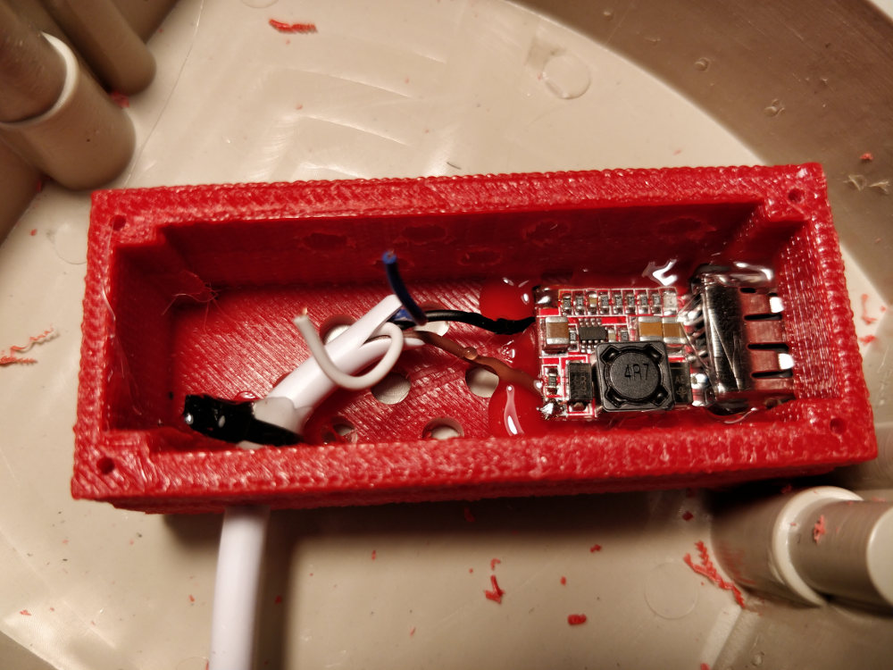
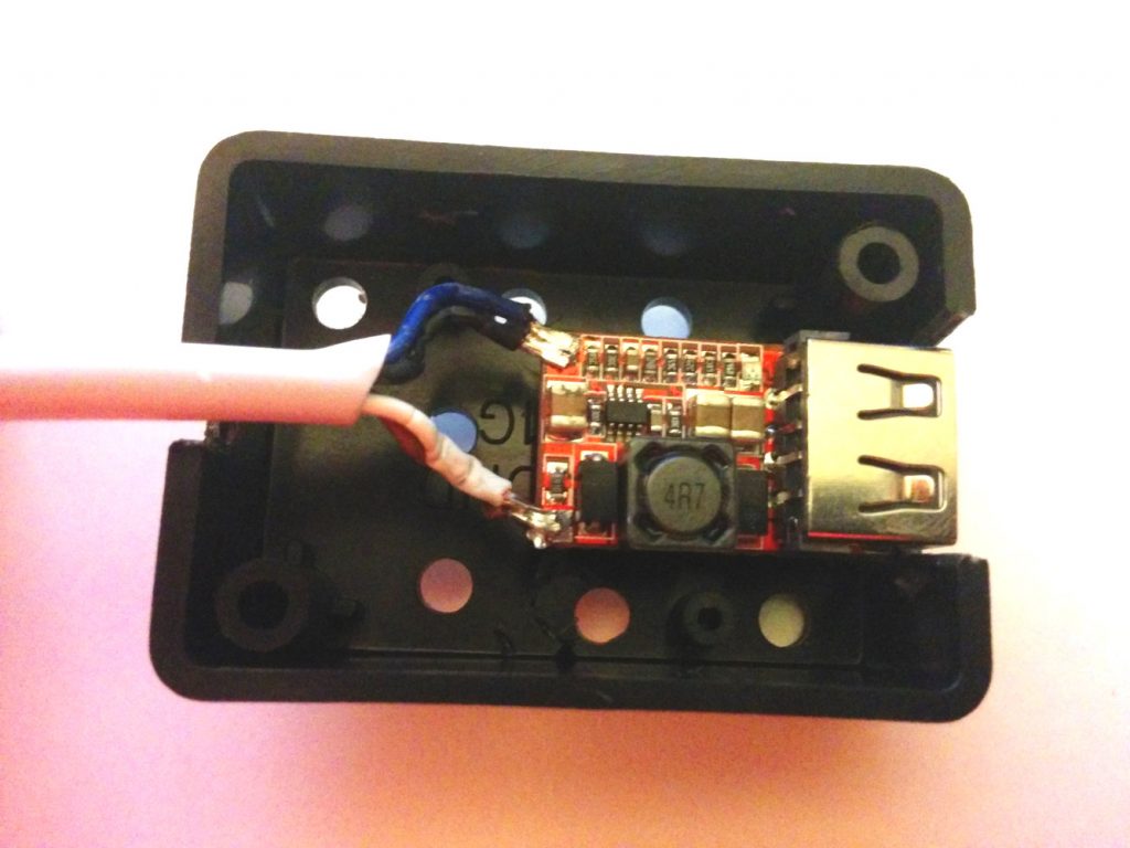
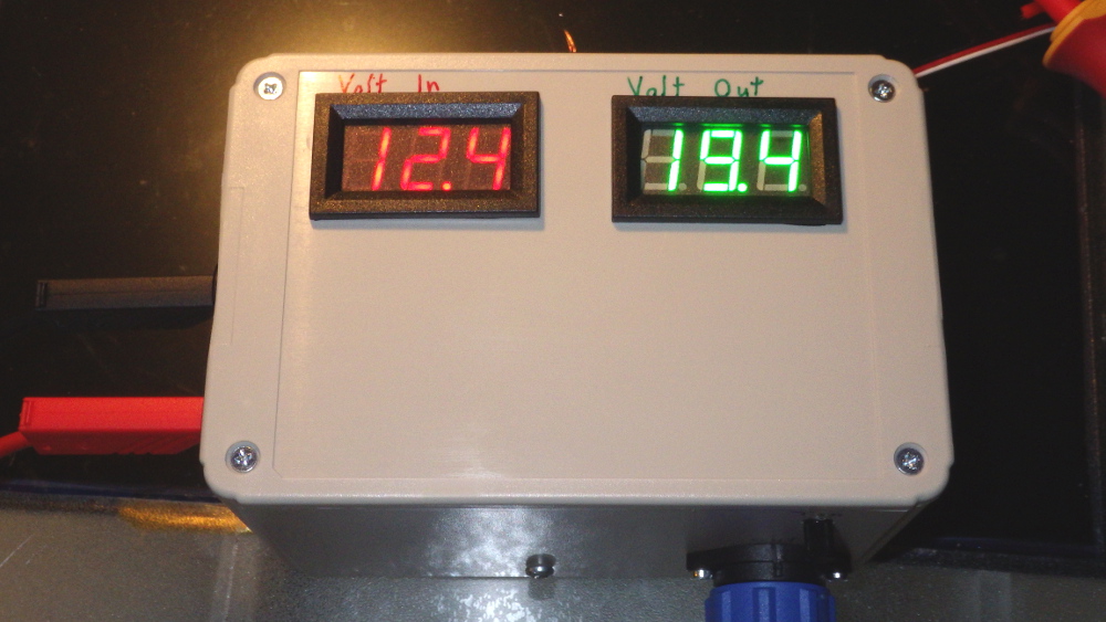
Die Platine liefert 24V, sowie maximal 100mA. Damit lässt sich ein ESP32 mit einem effizienten, vorgeschalteten 5V StepDown Wandler versorgen.
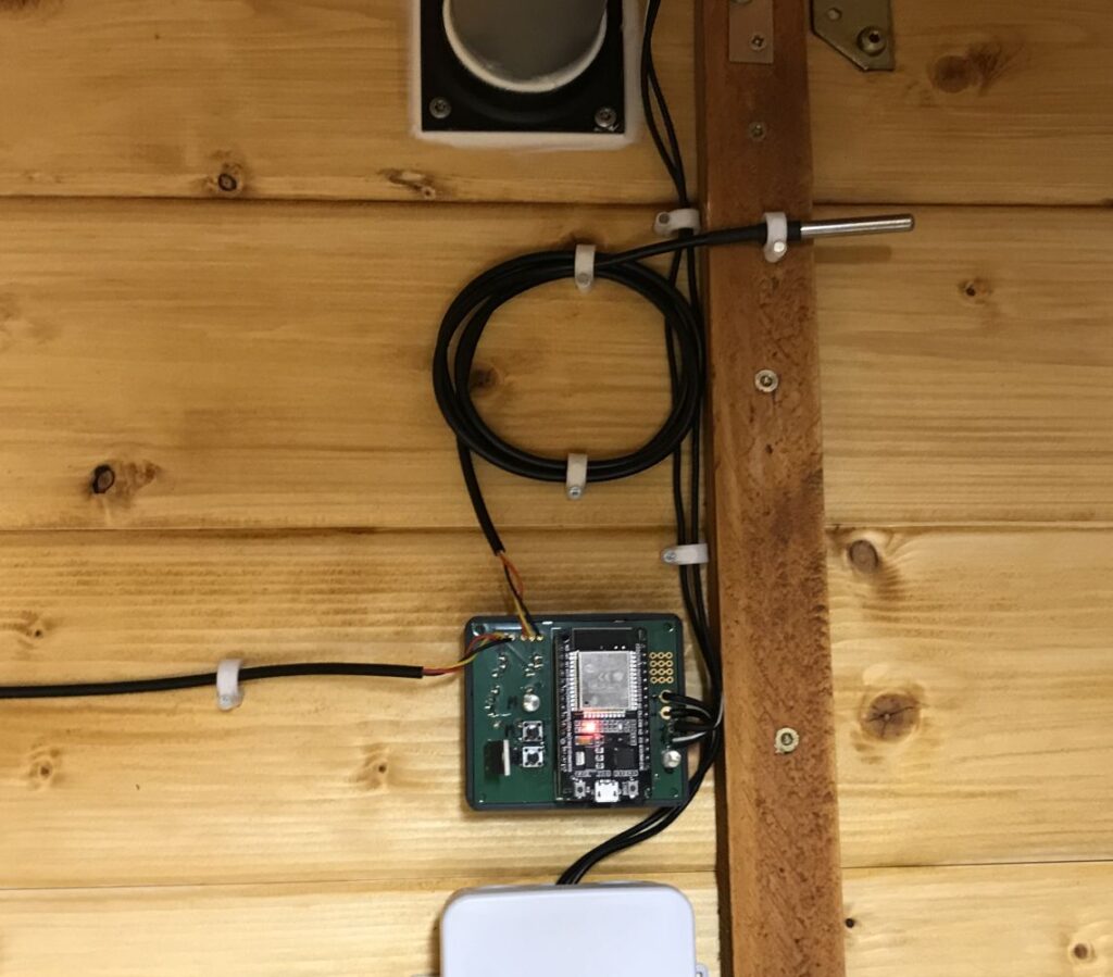
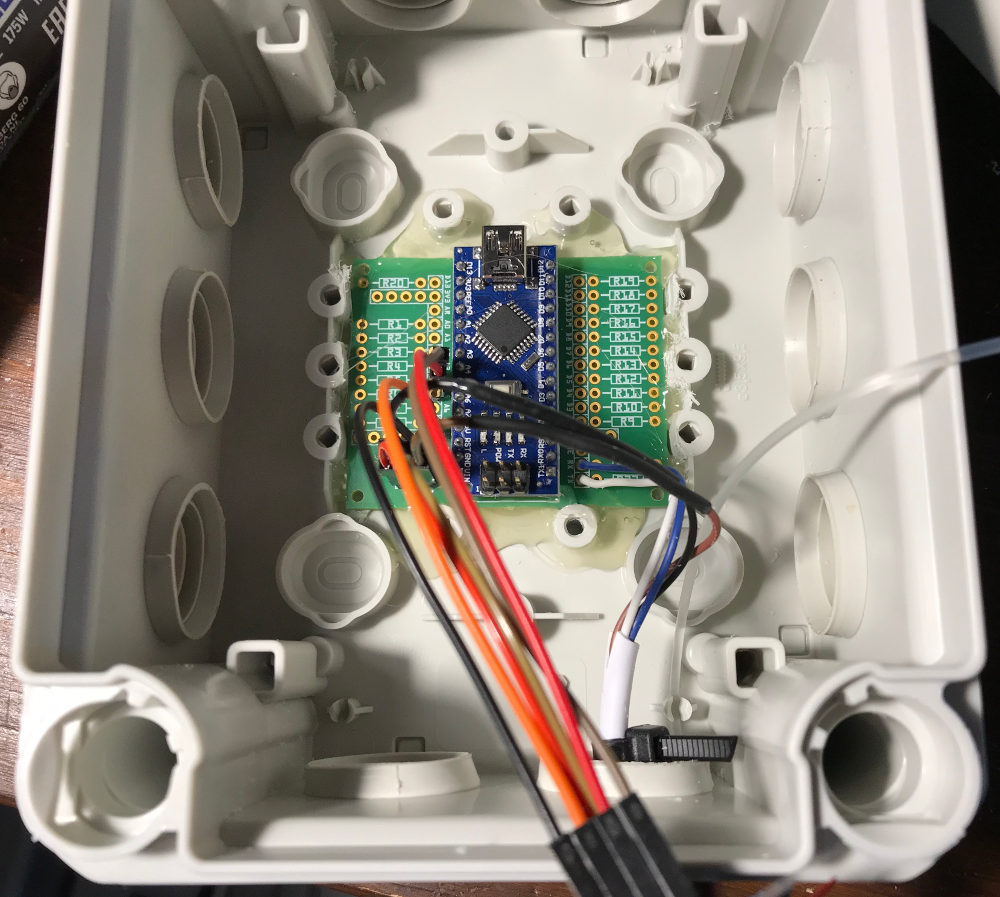
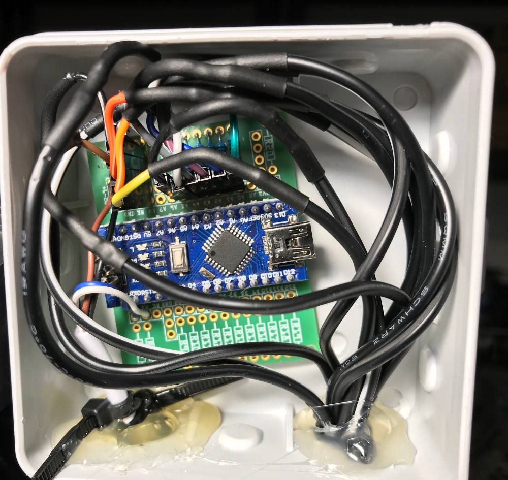
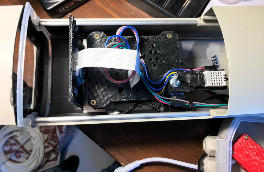
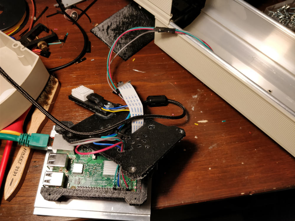
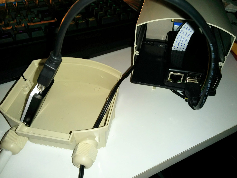
Als Microcontroller habe ich mich für einen ESP32 mit 38 Pins entschieden.
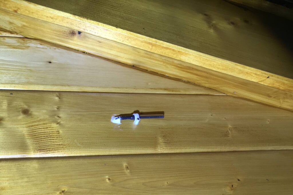
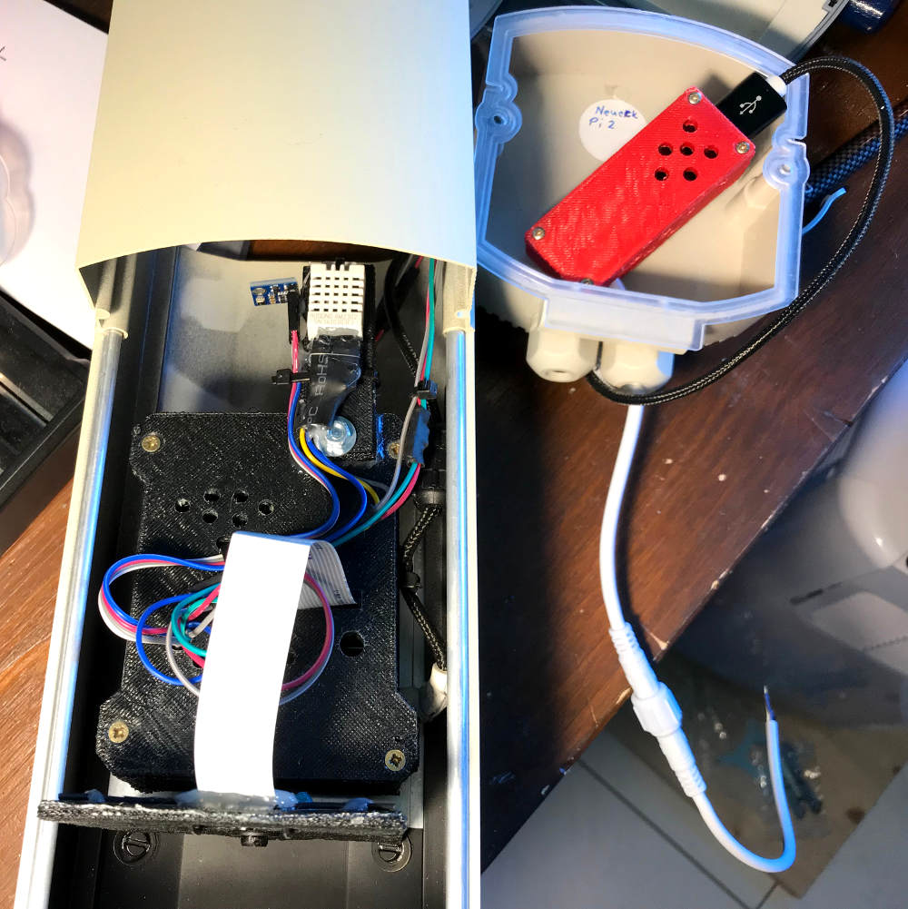
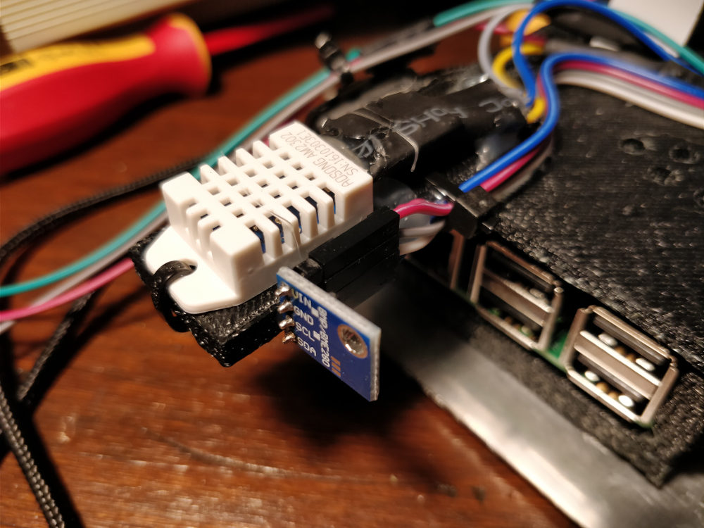
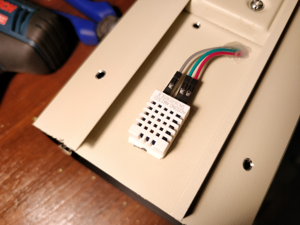
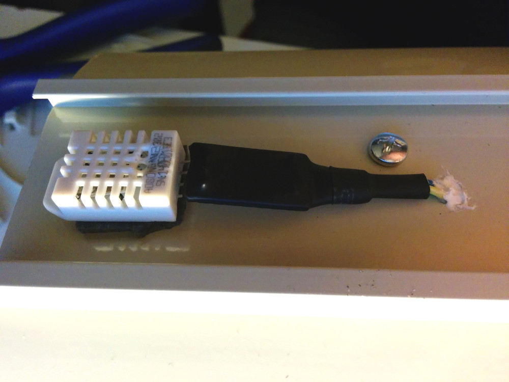
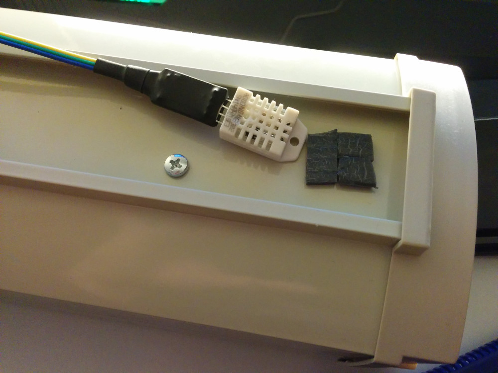
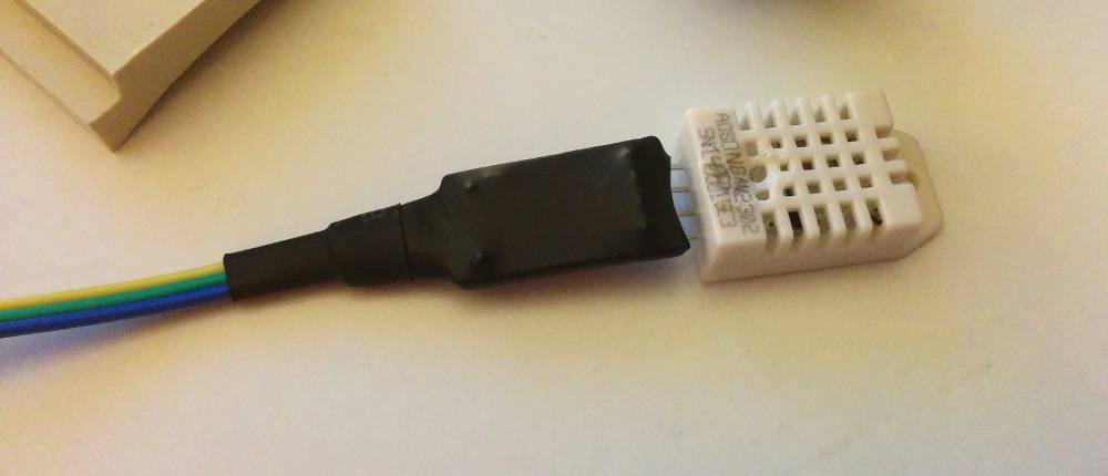
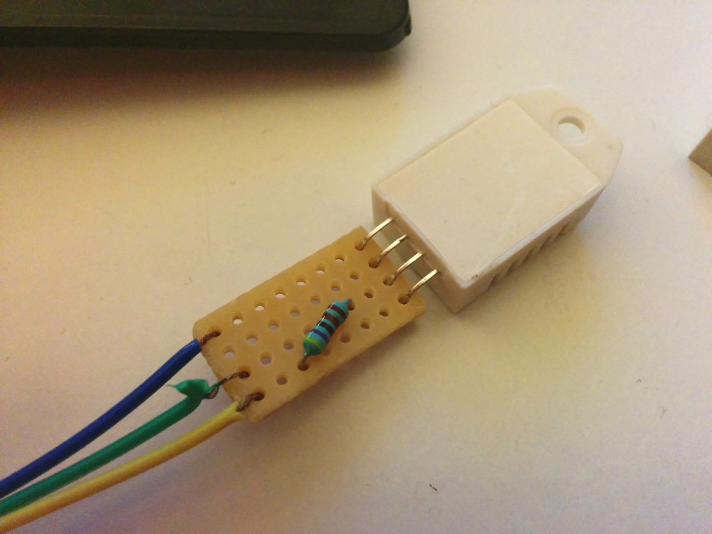
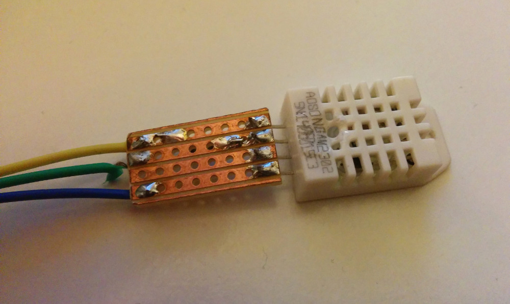
Um die Temperatur, Luftfeuchtigkeit, sowie Luftdruck zu erfassen, verwende ich einen BME280 Sensor.
Damit das Garagentor nicht nur über das Webinterface schaltbar ist, gibt es auf der Platine weitere Pins, an die sich externe Schalter anschließen lassen.
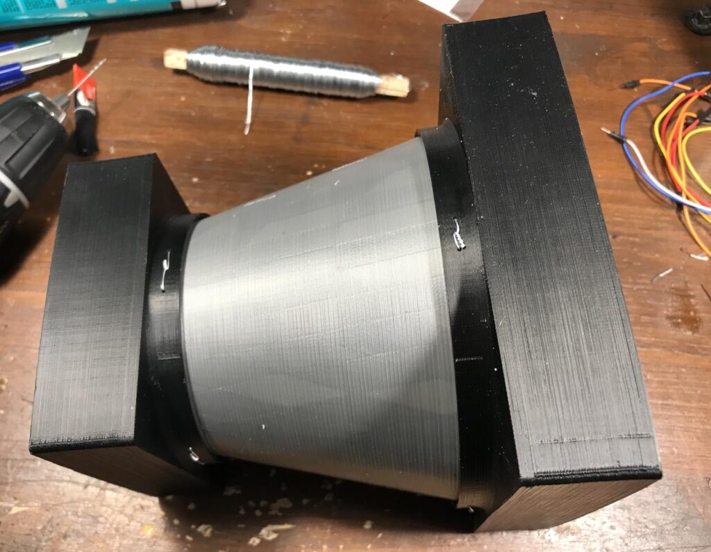
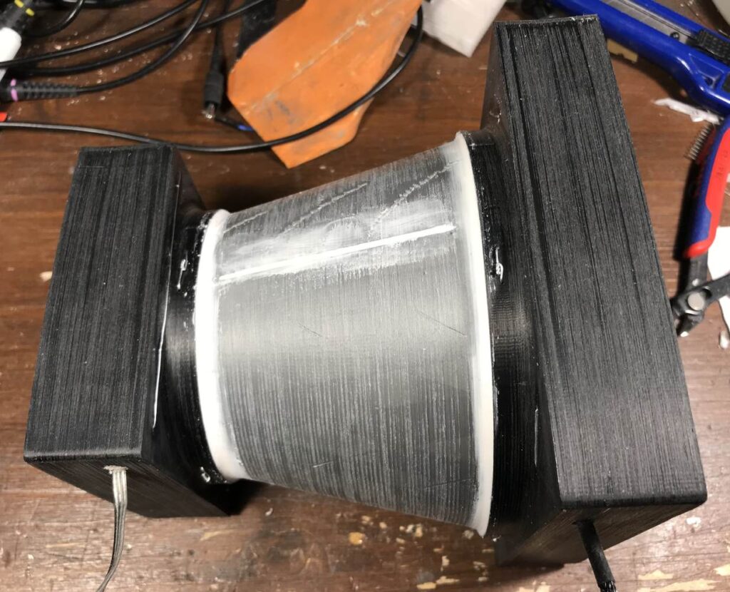
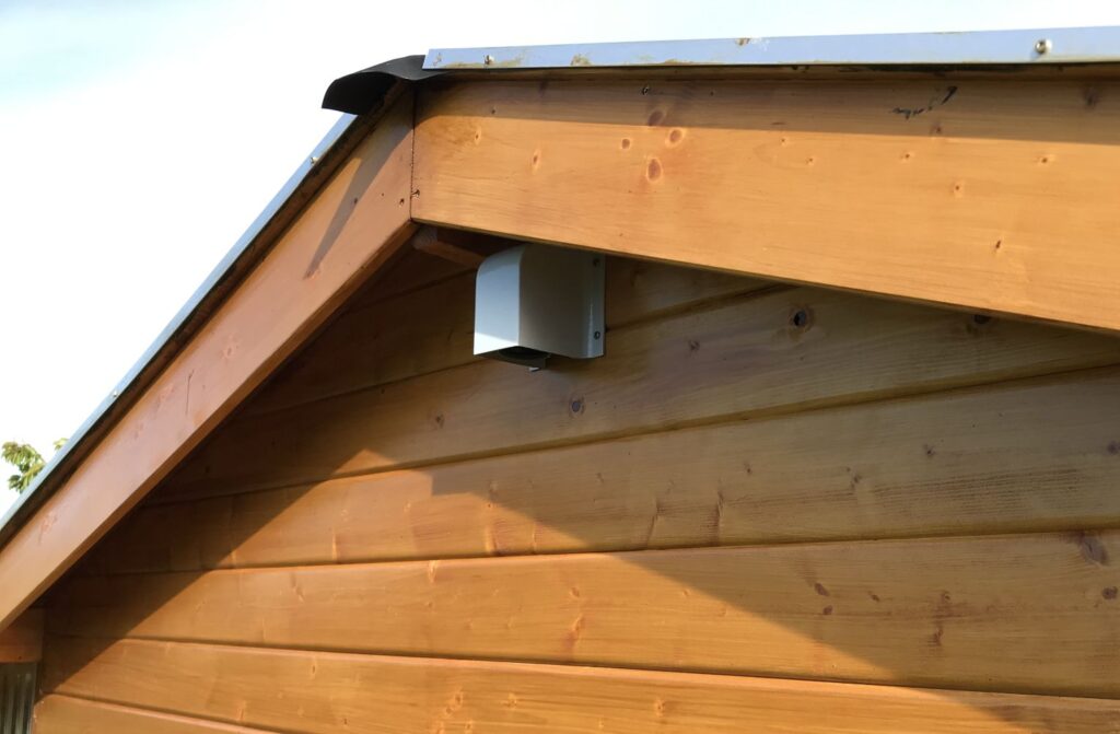
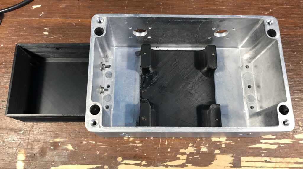
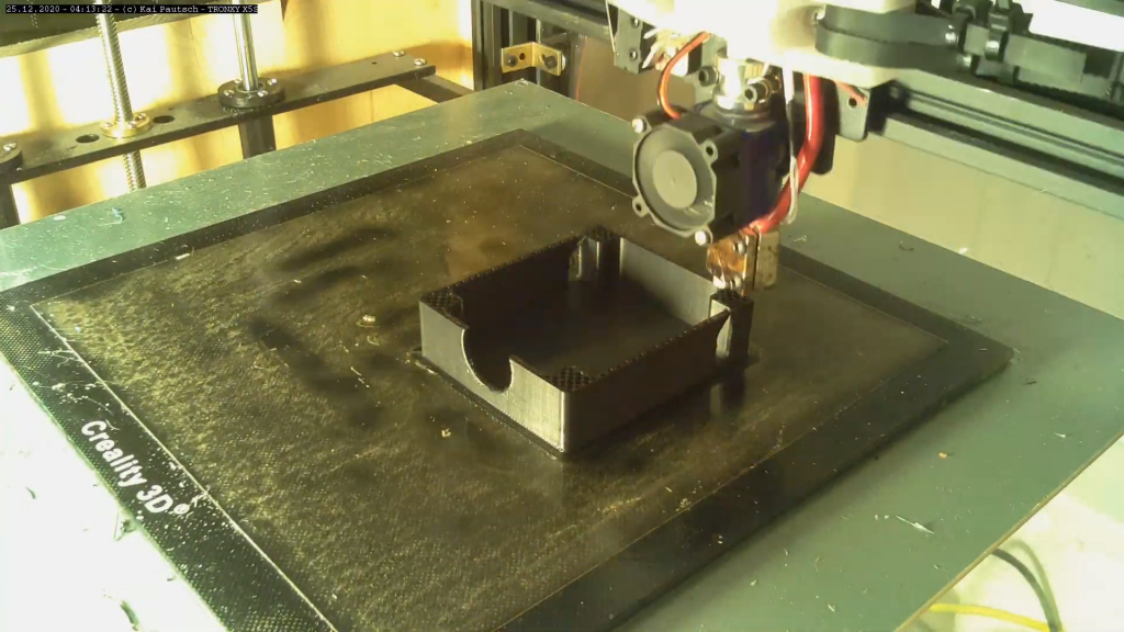
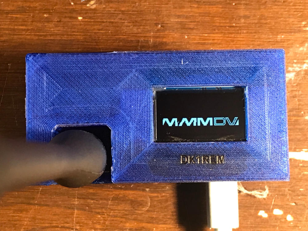
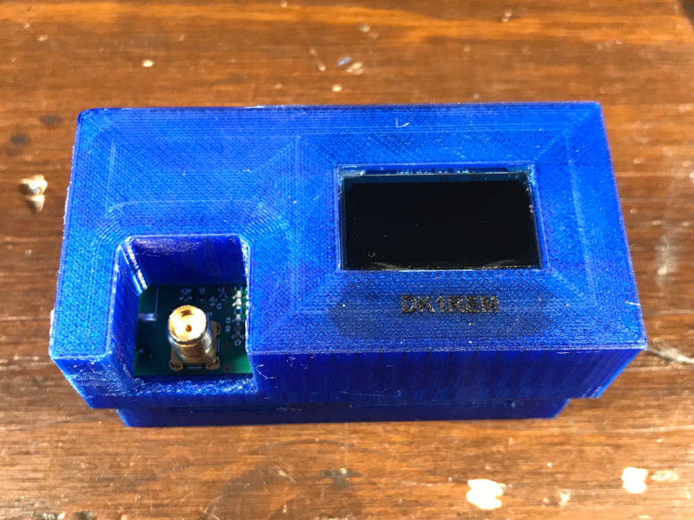
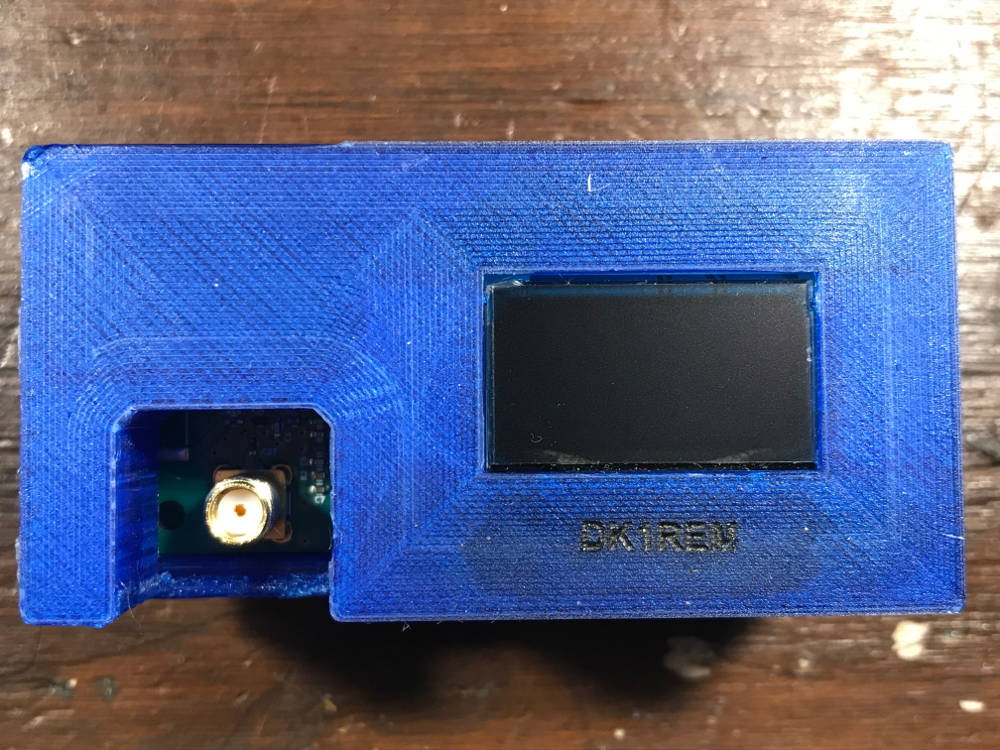
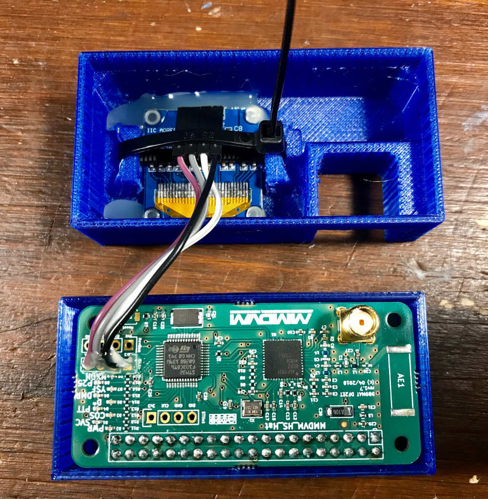
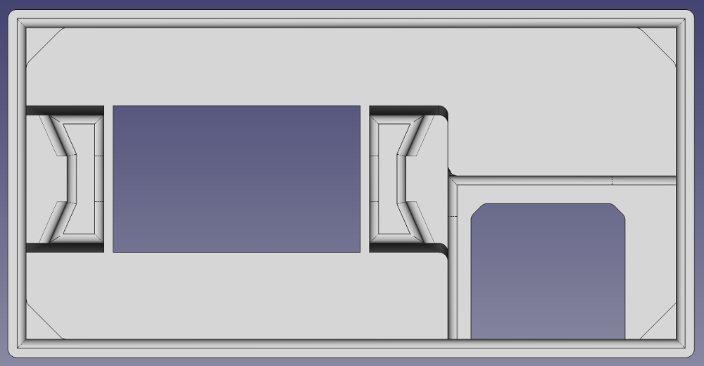
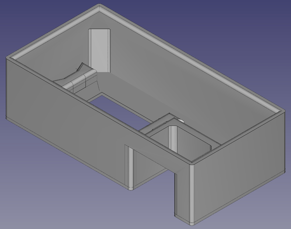
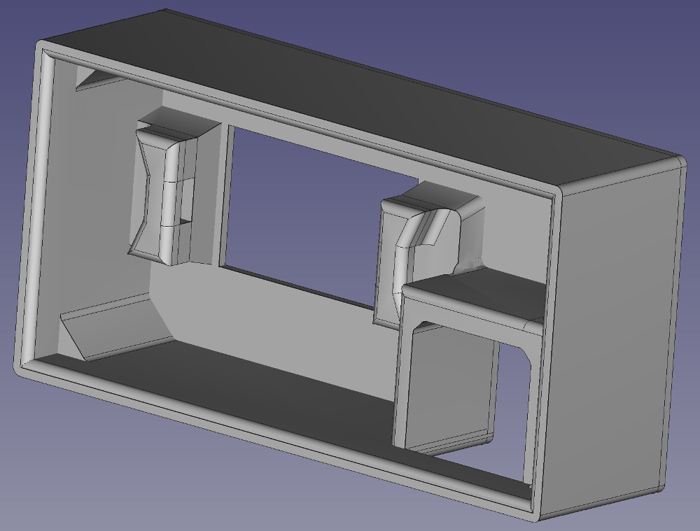
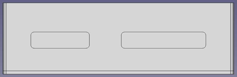
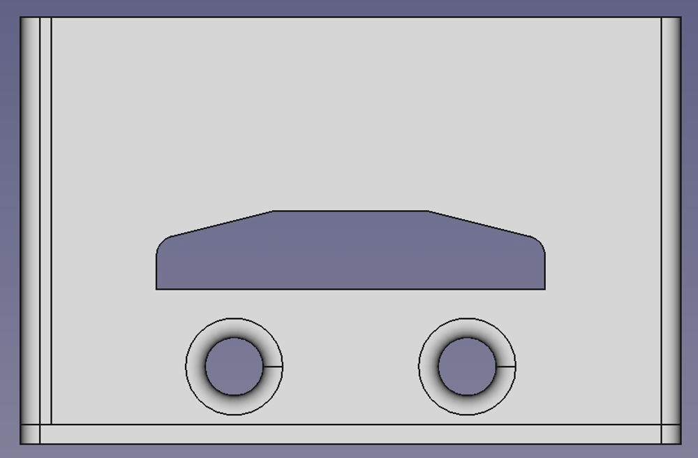
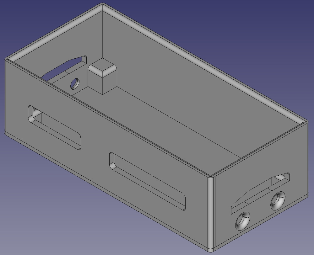
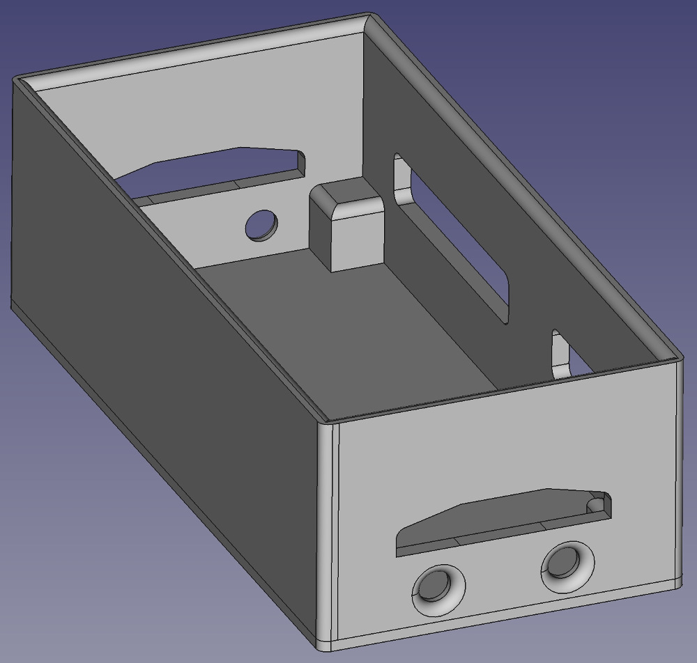
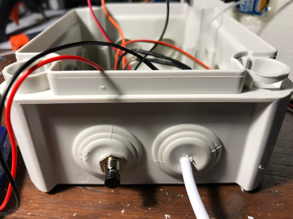
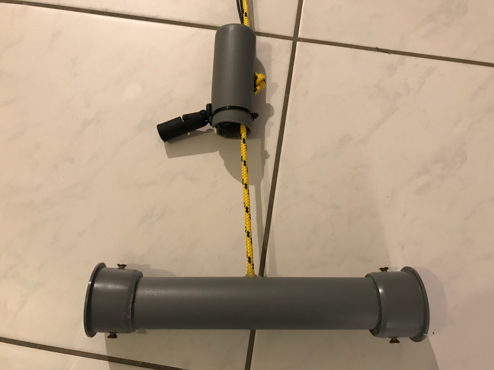
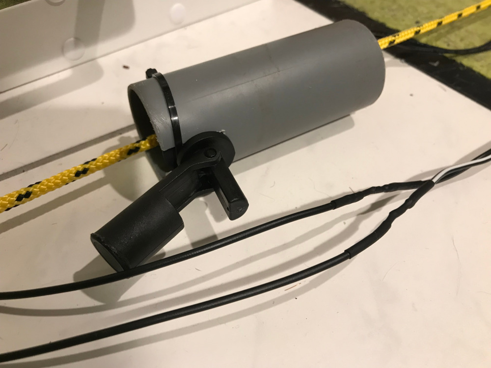
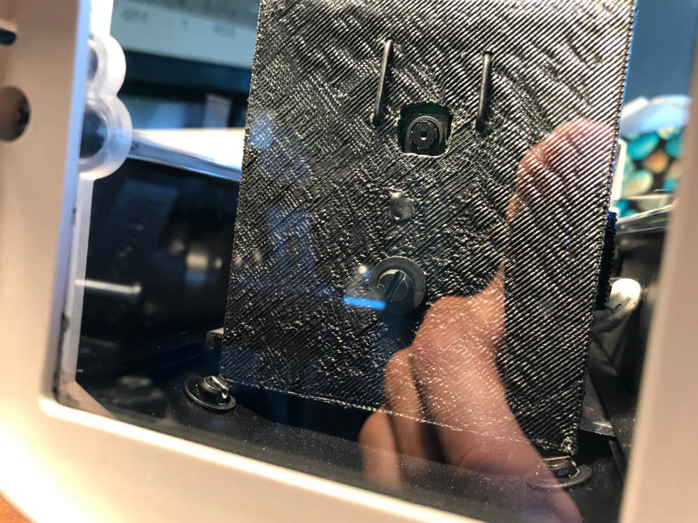
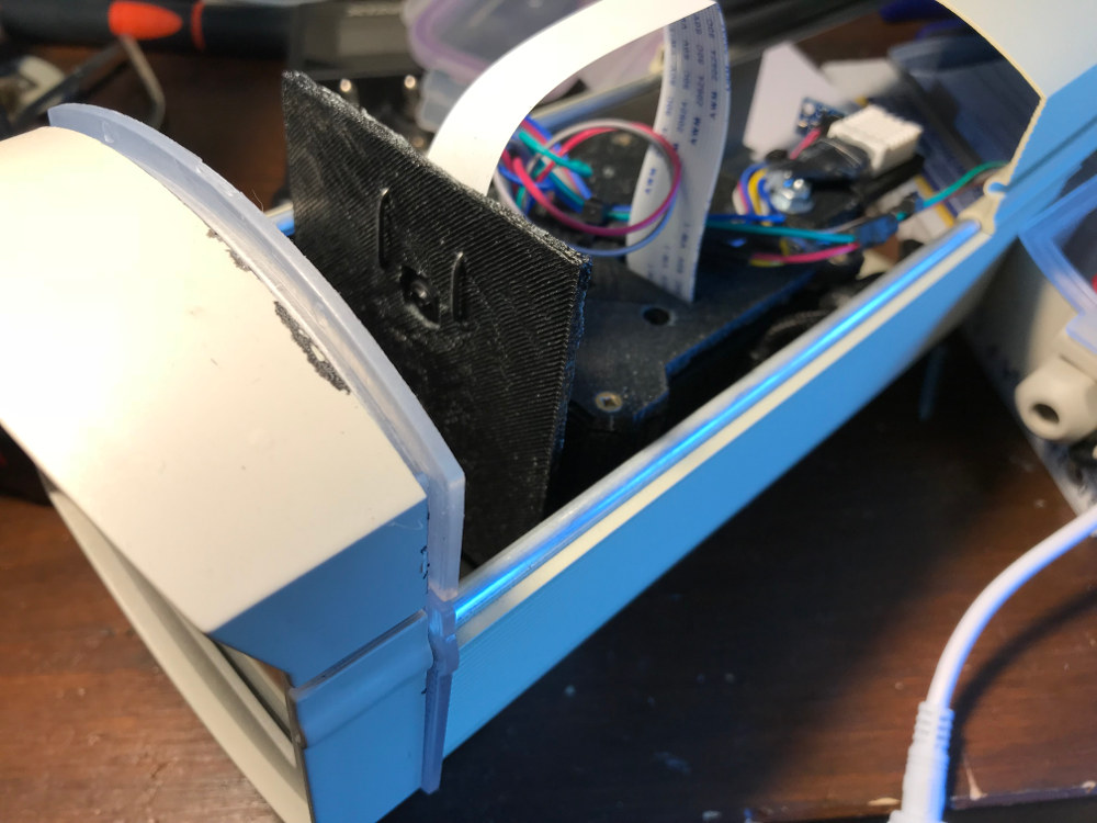
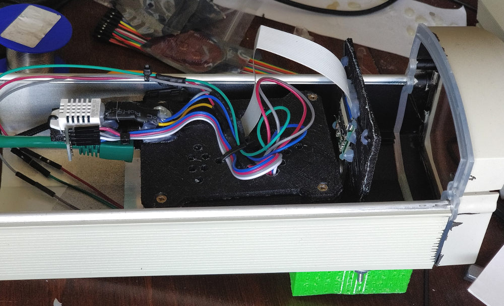
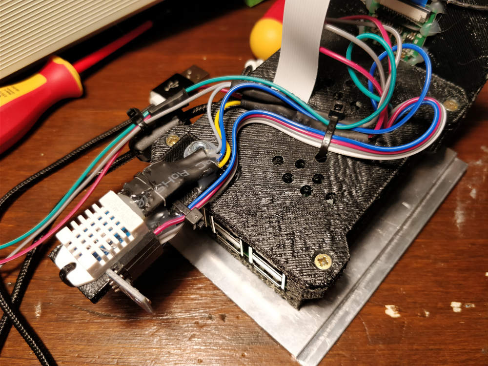
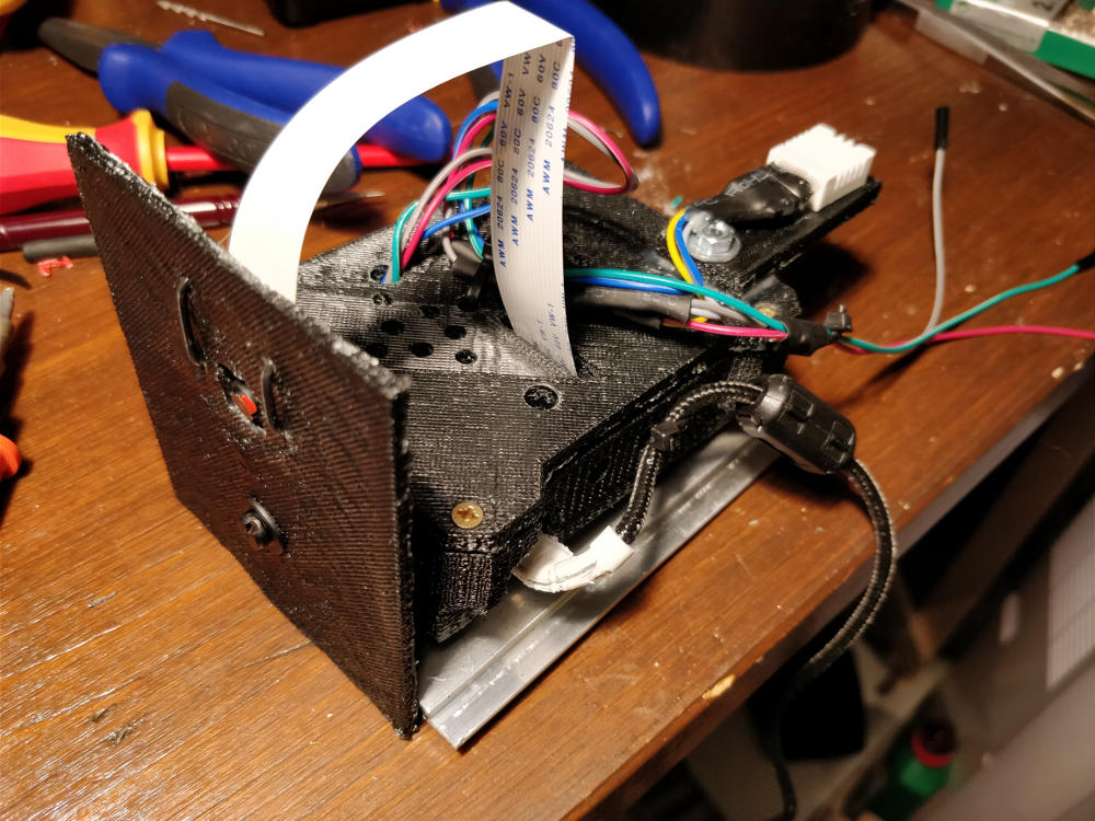
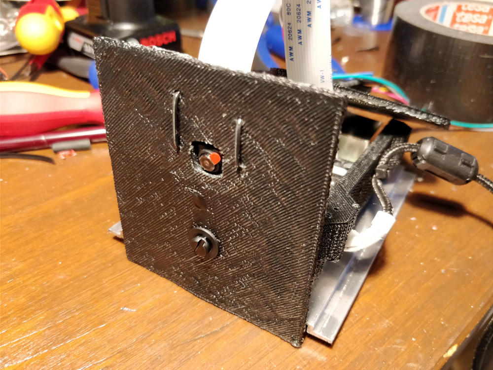
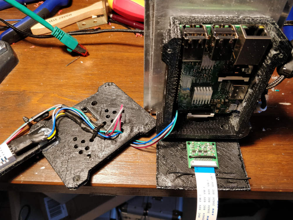
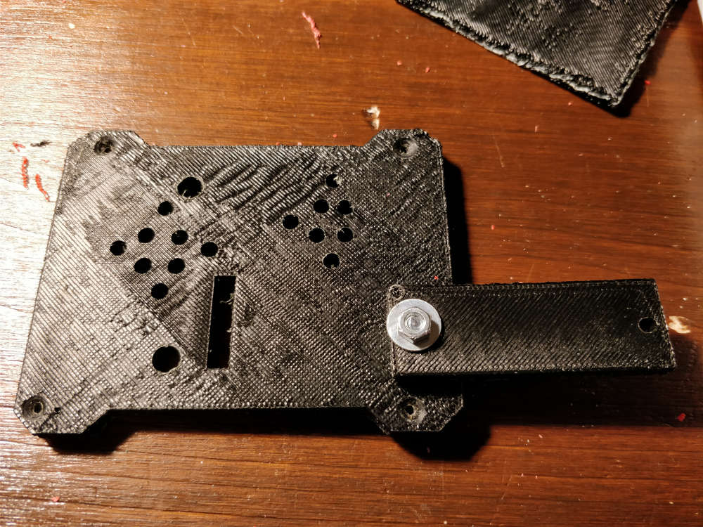
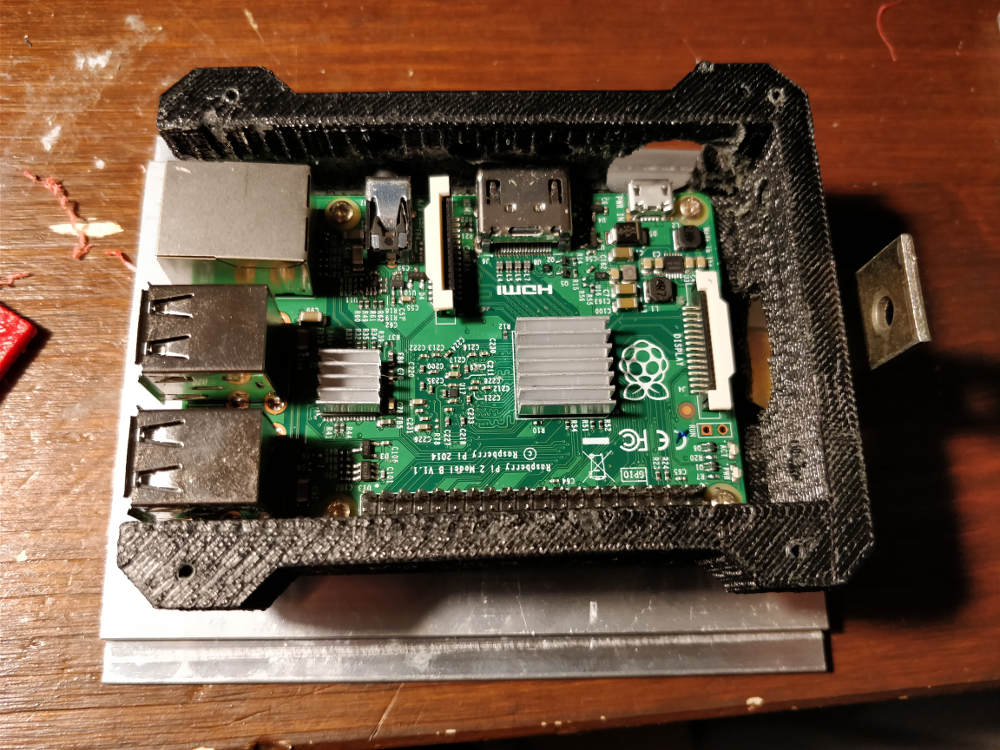
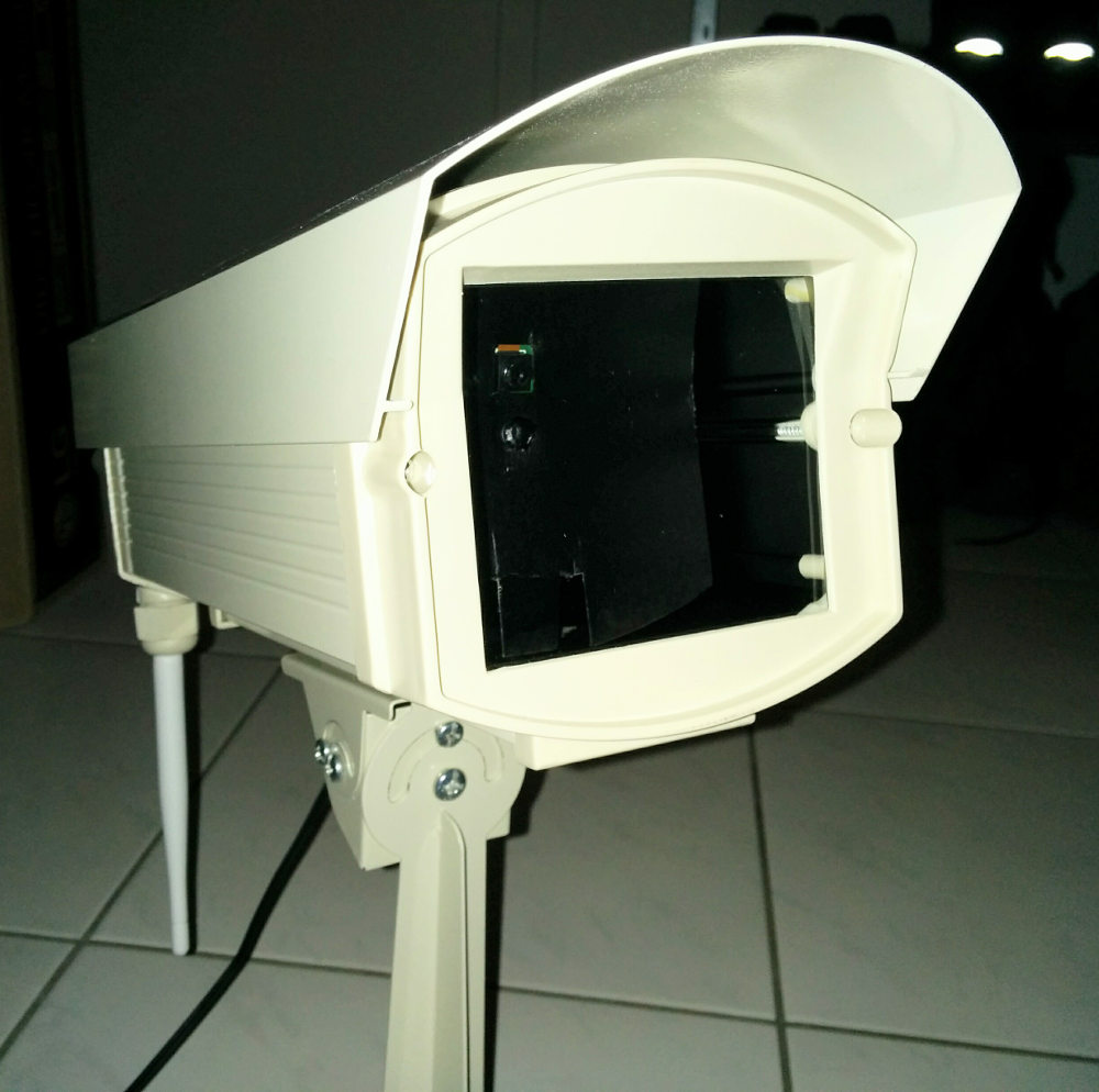
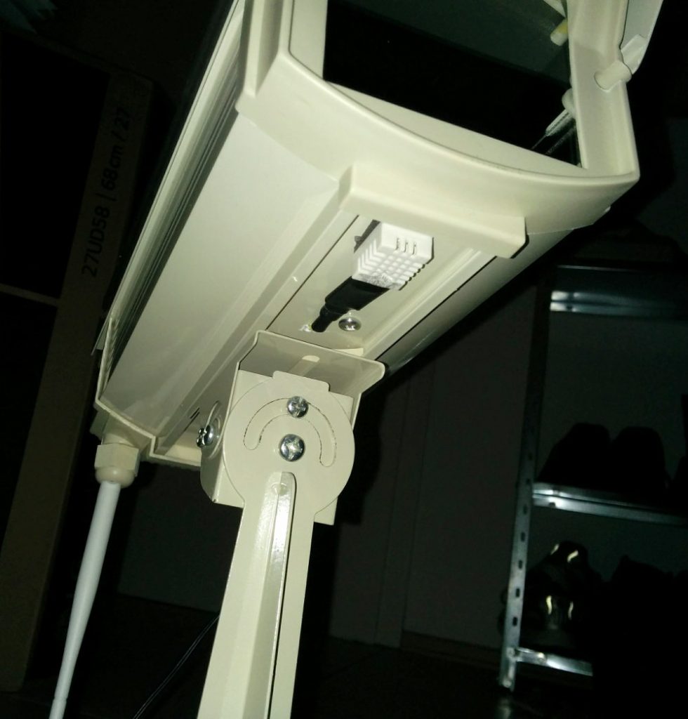
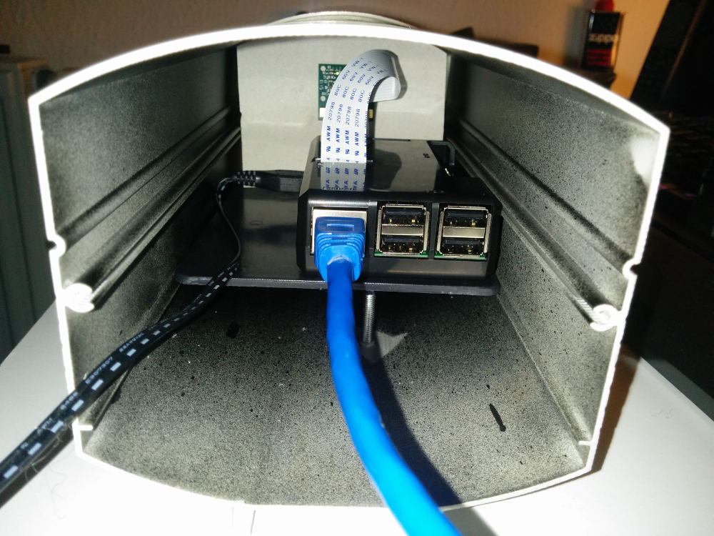
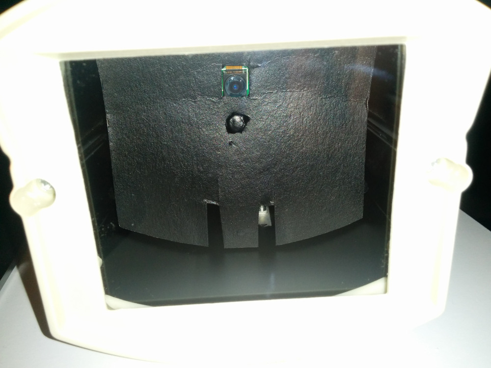
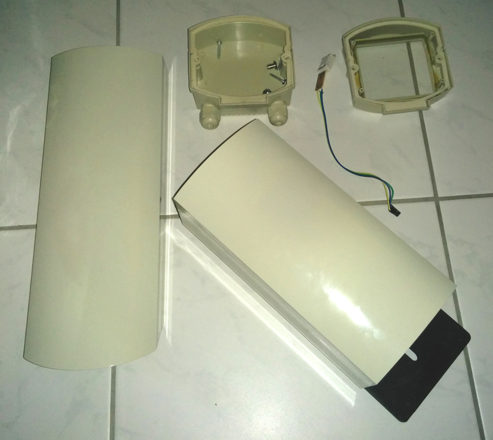
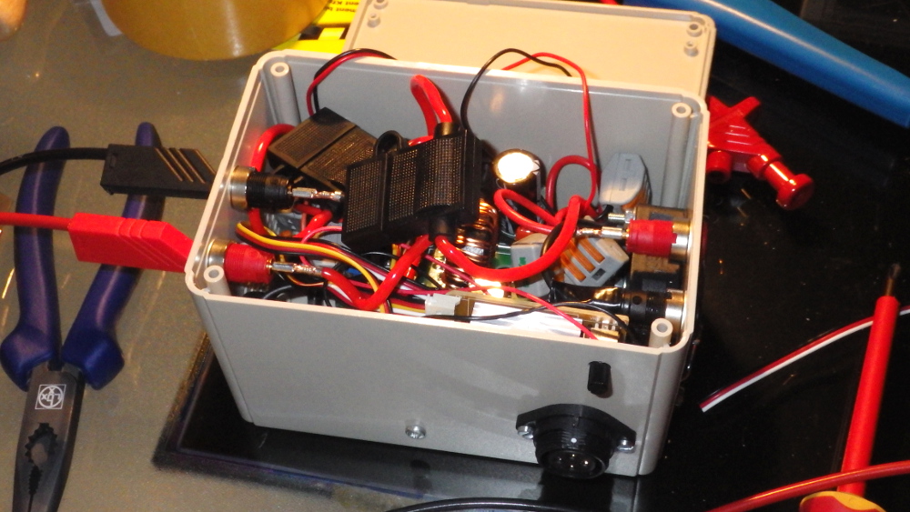
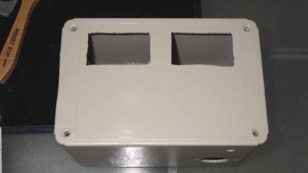
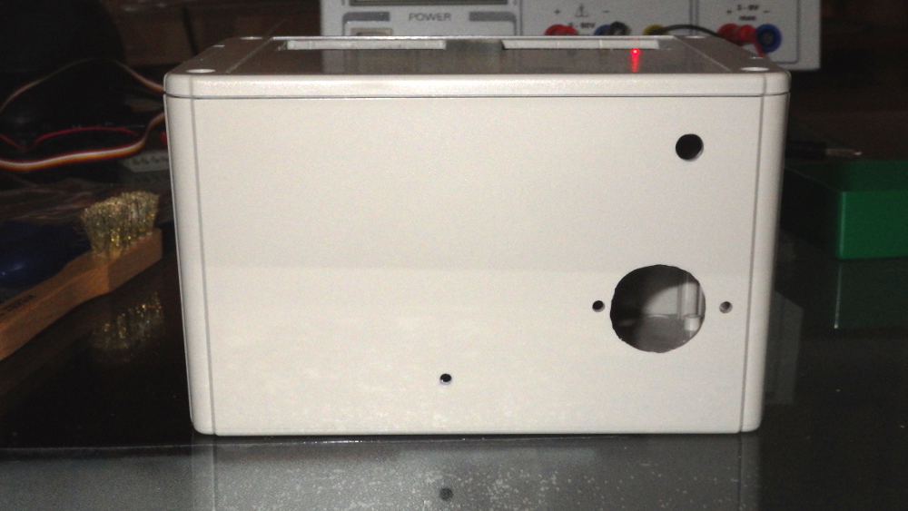
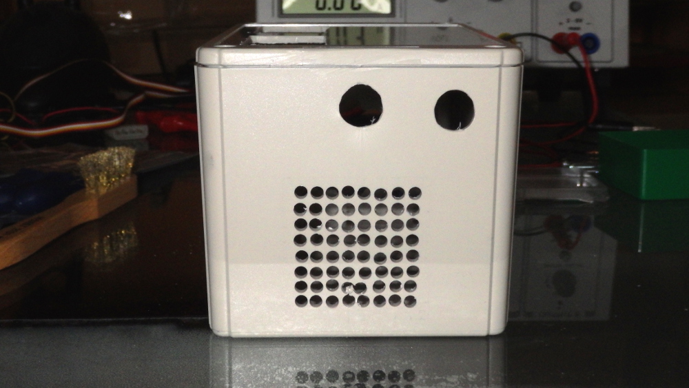
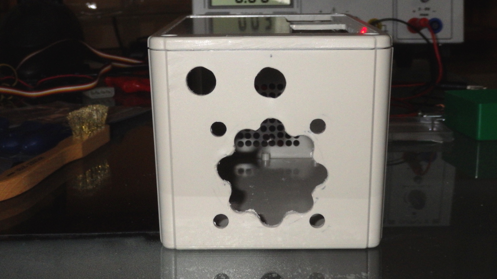
Gehäuse
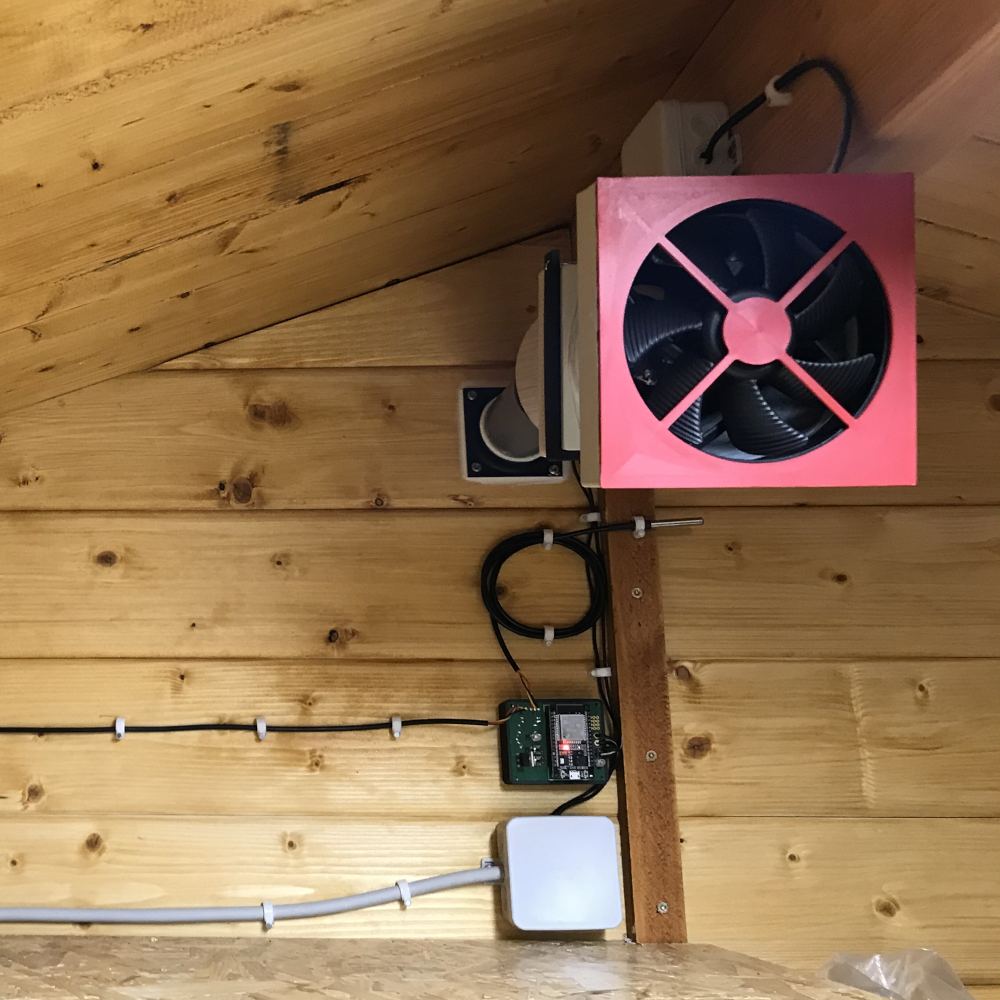
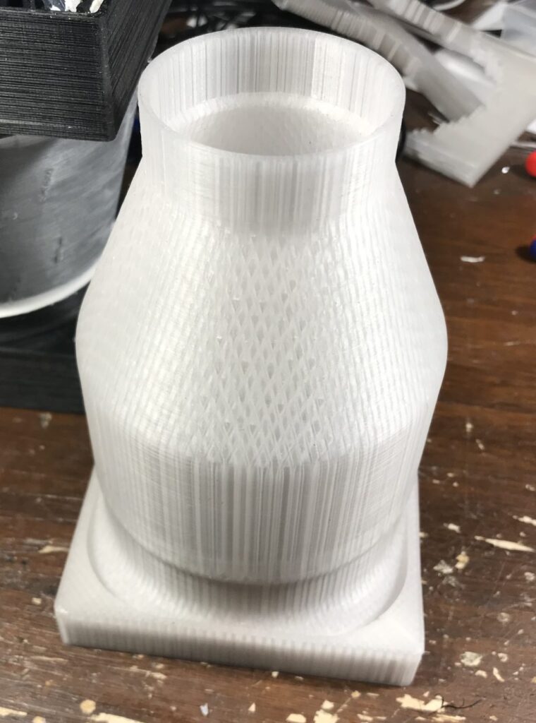
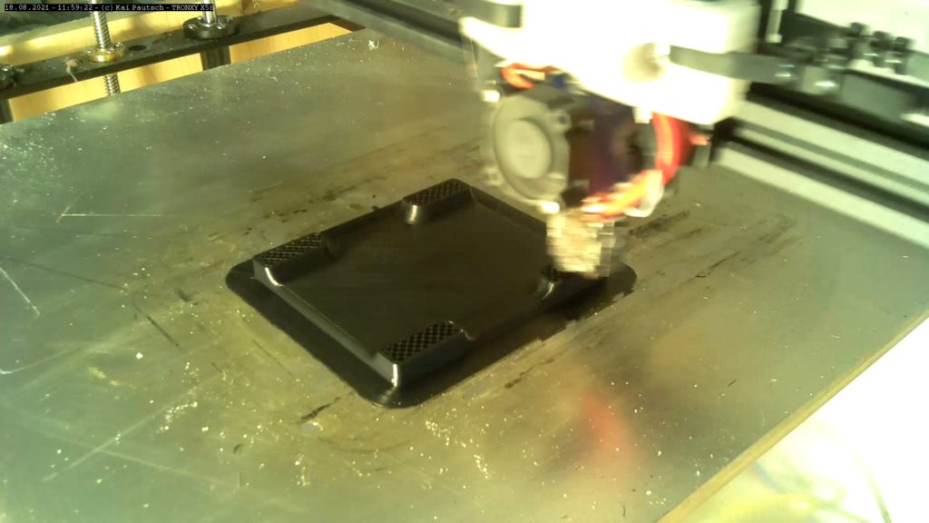
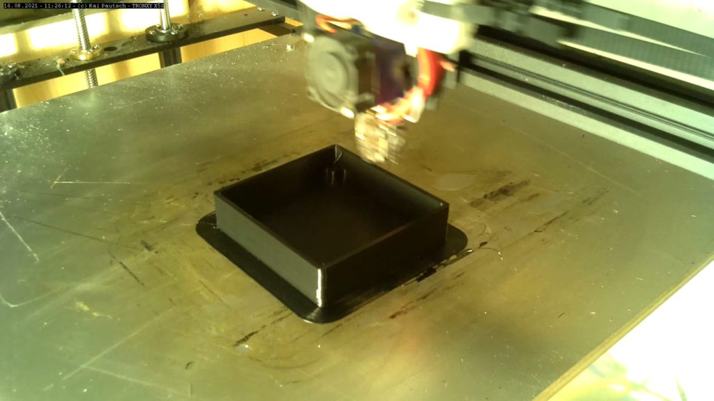
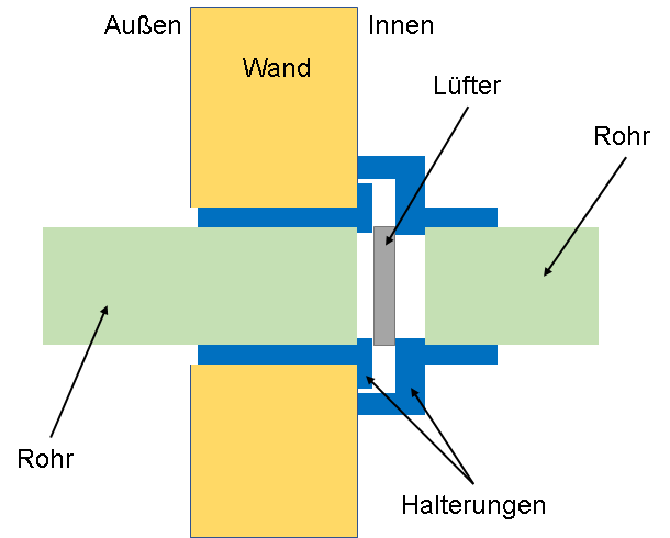
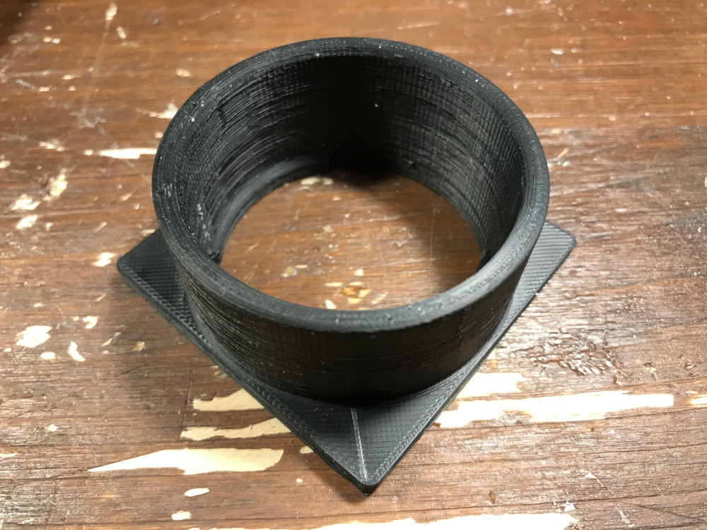
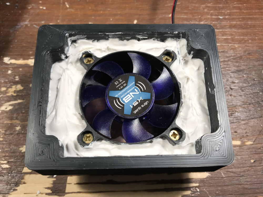
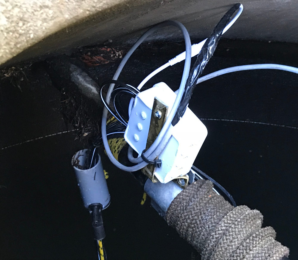
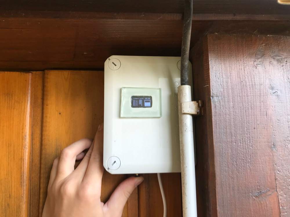
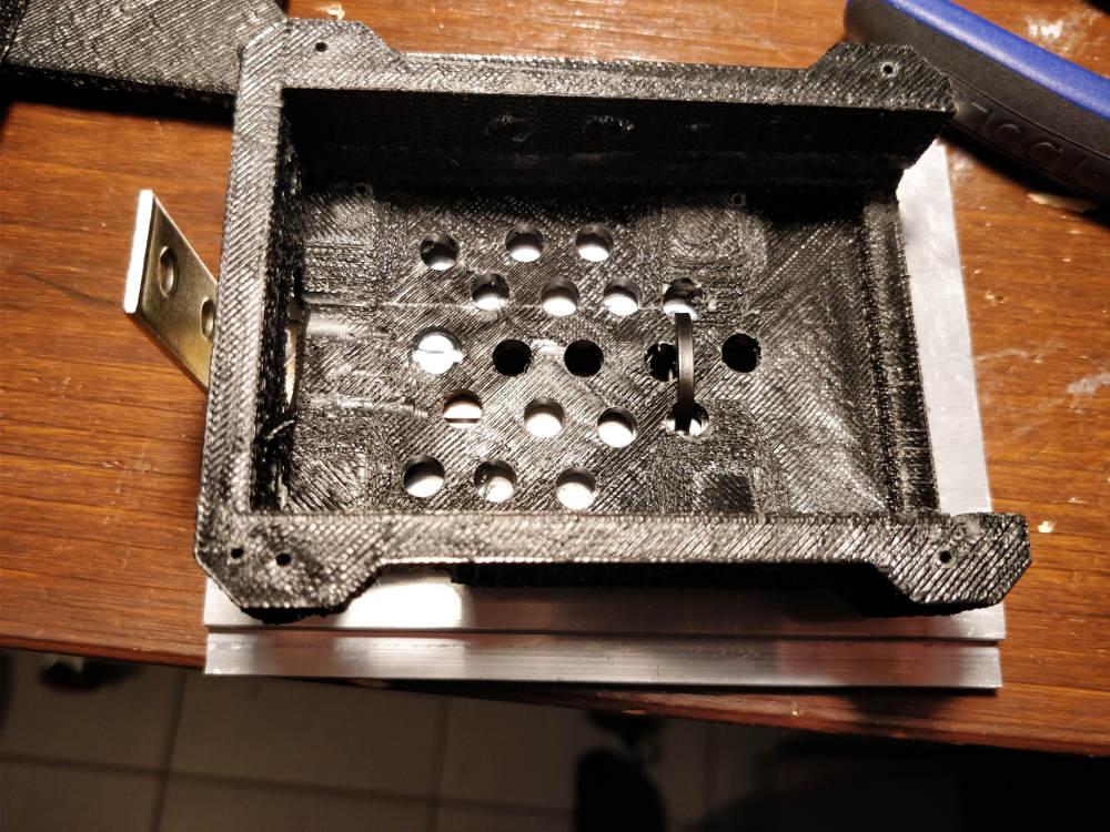
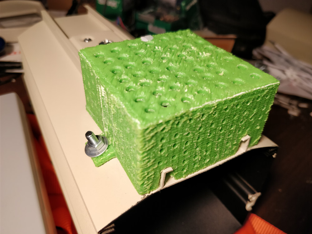
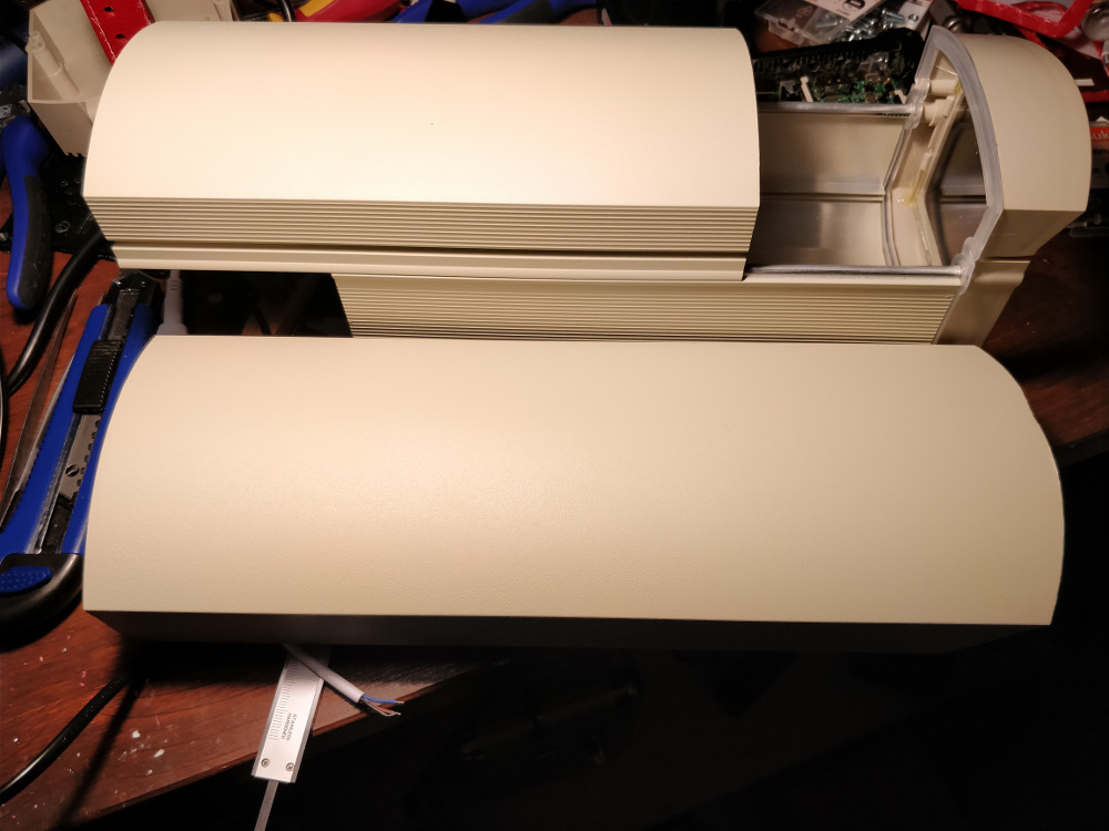
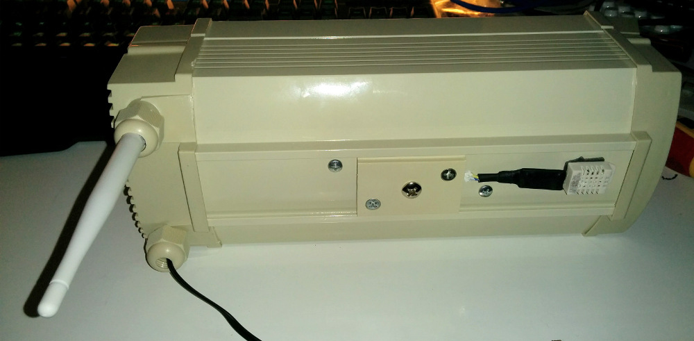
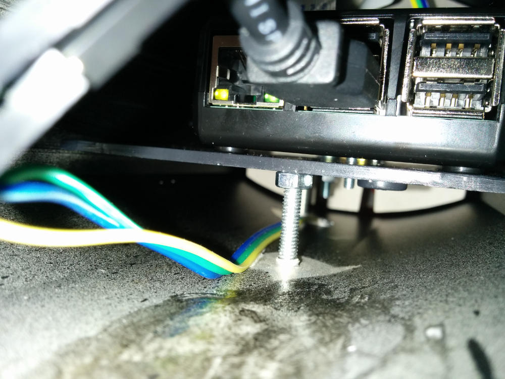
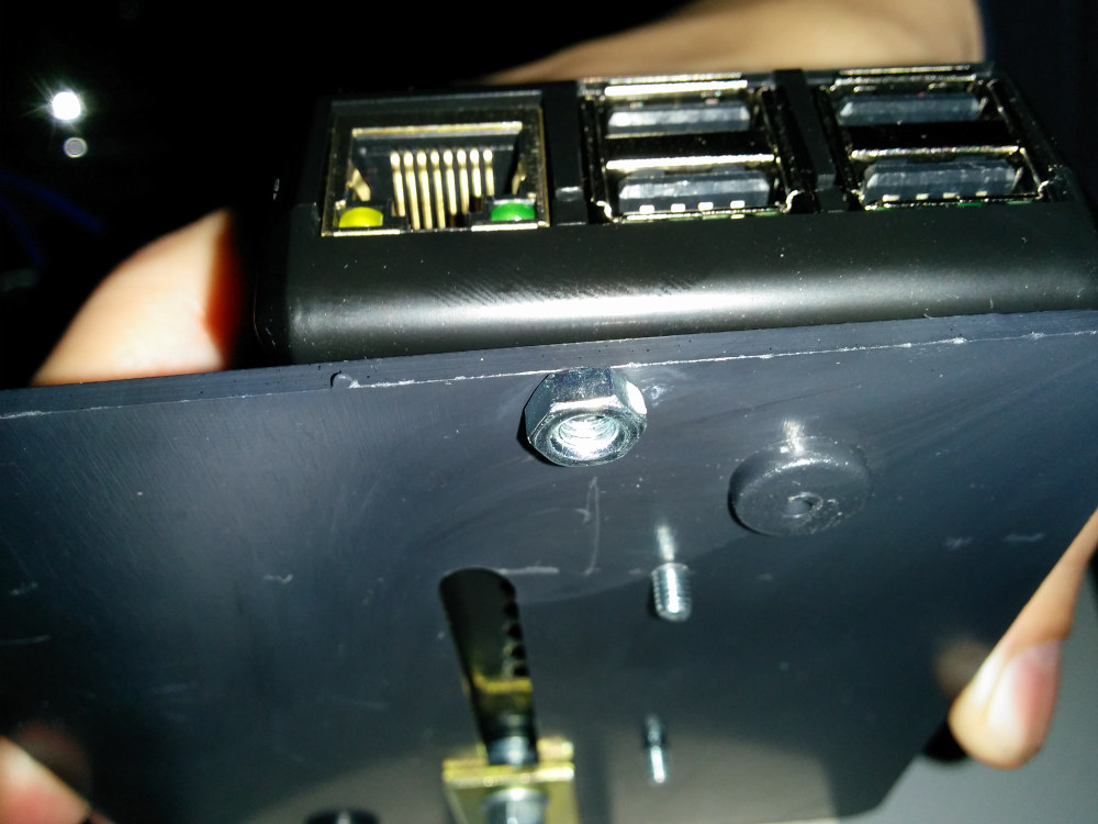
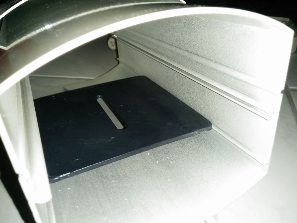
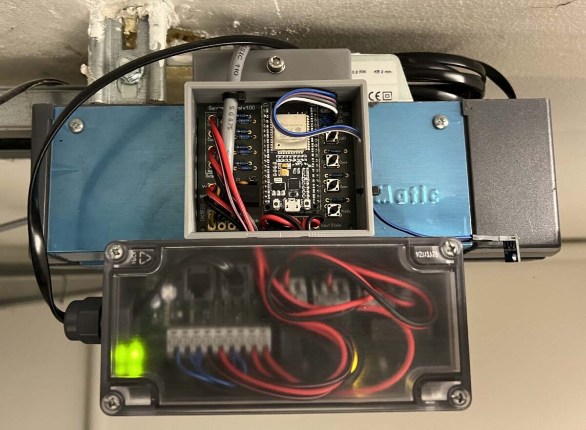
Praktischerweise besitzt der Garagentorantrieb oberhalb ein Blech, mit Loch, an dem ich das Gehäuse befestigt habe. Leider ist das Blech etwas innenliegend, somit muss das Gehäuse dort, wo es verschraubt wird, etwas dicker sein. Um es besser drucken zu können, habe ich das Gehäuse und den Abstandshalter separat gedruckt.
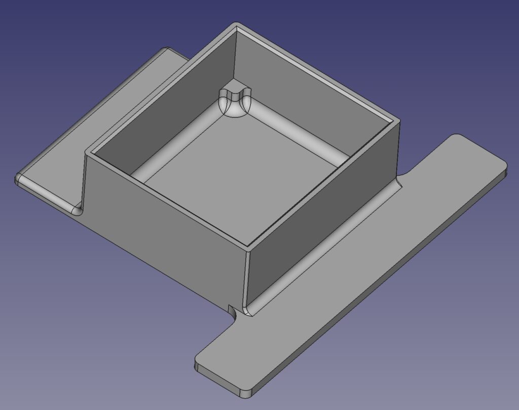
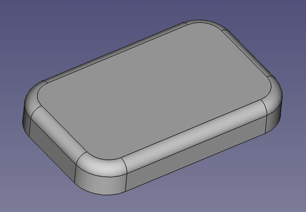
Einen Deckel habe ich noch nicht gedruckt, das werde ich hier ergänzen, sobald ich ihn gedruckt habe.
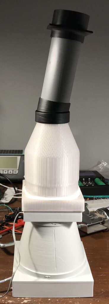
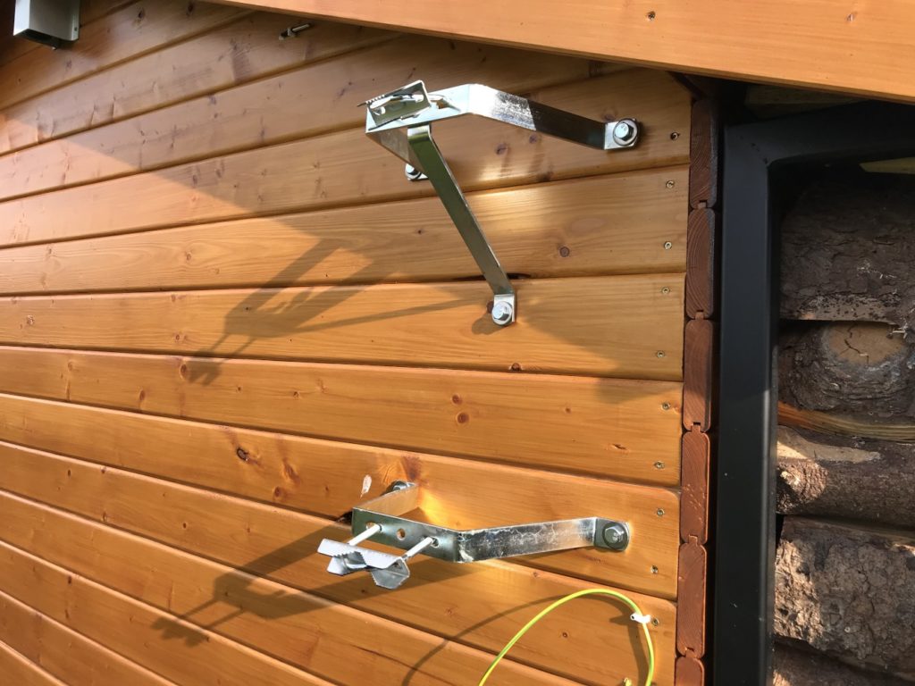
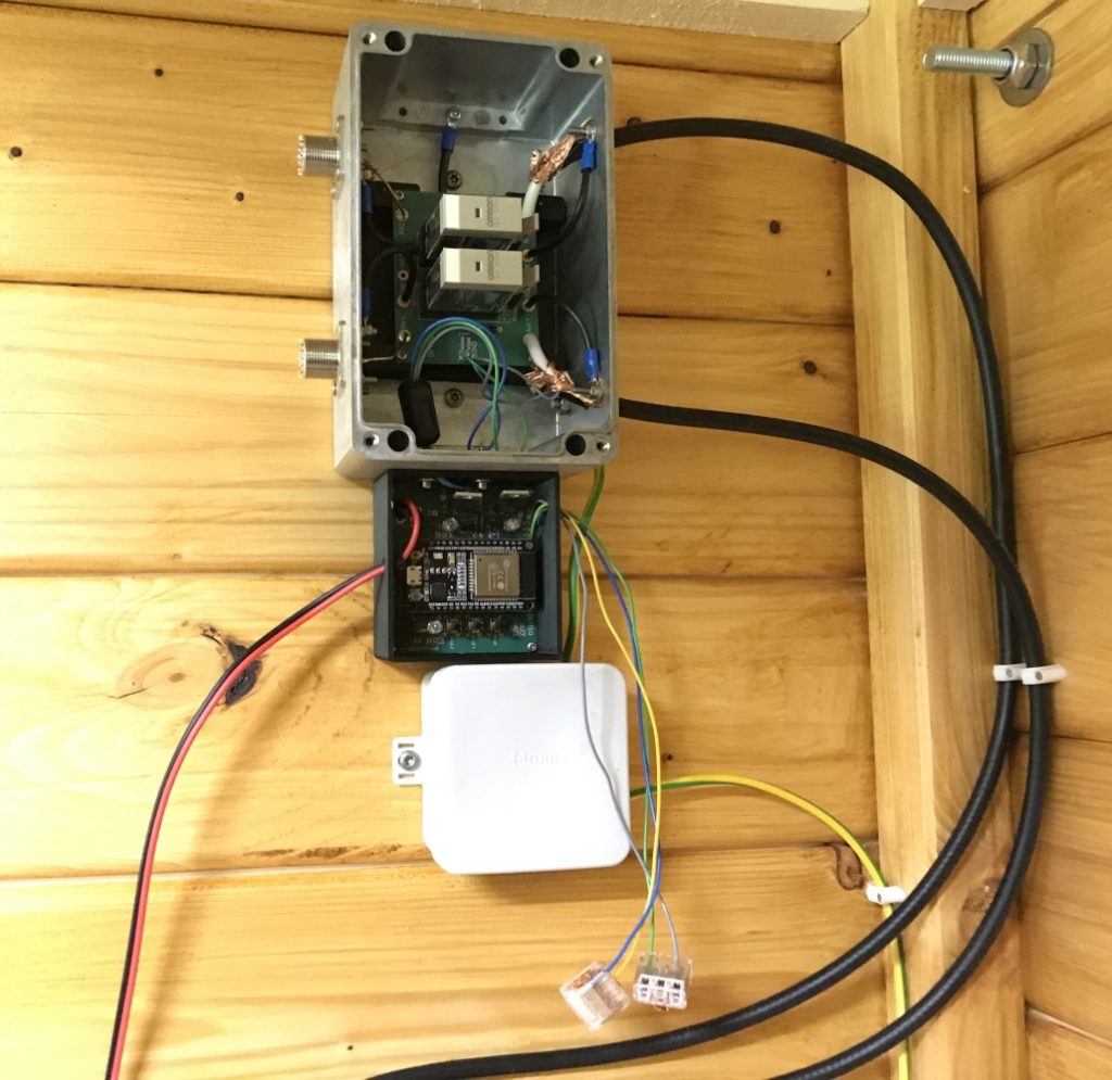
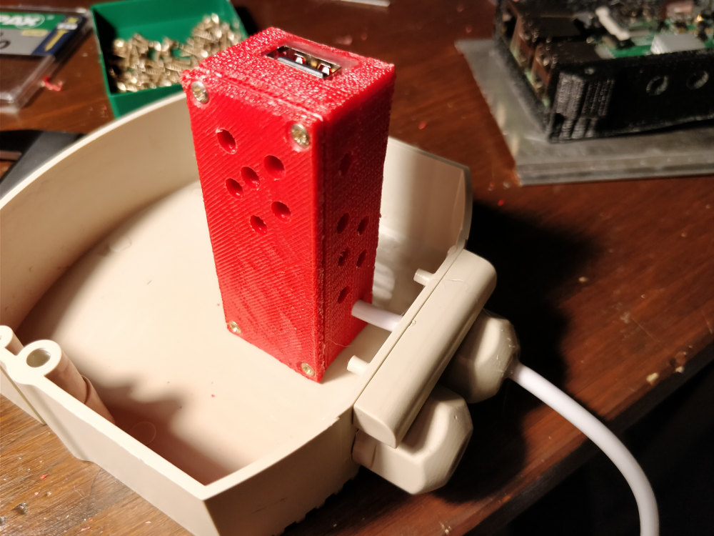
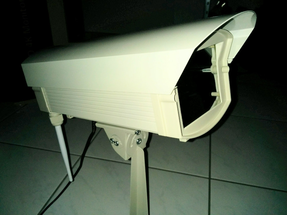
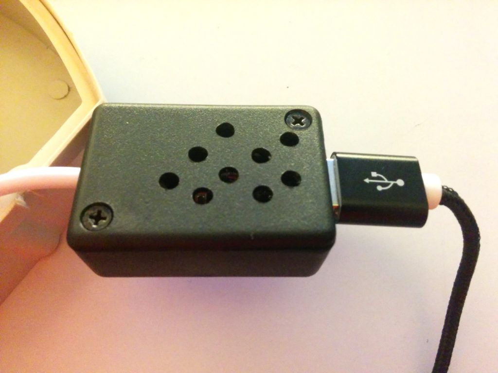
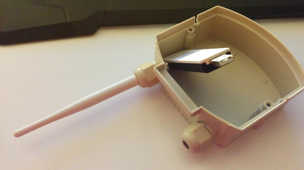
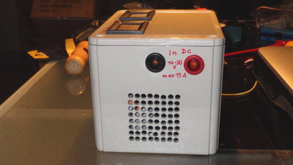
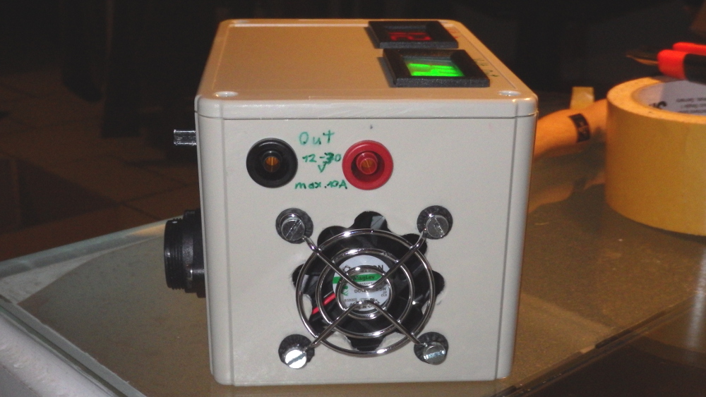
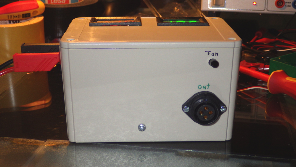
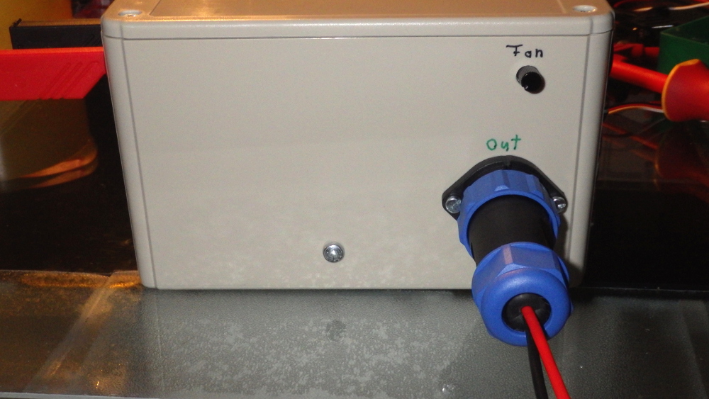
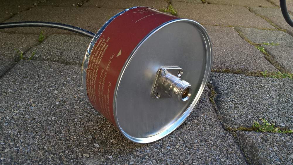
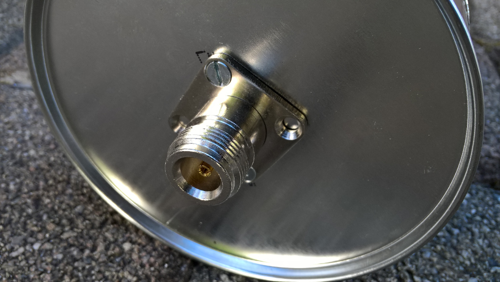
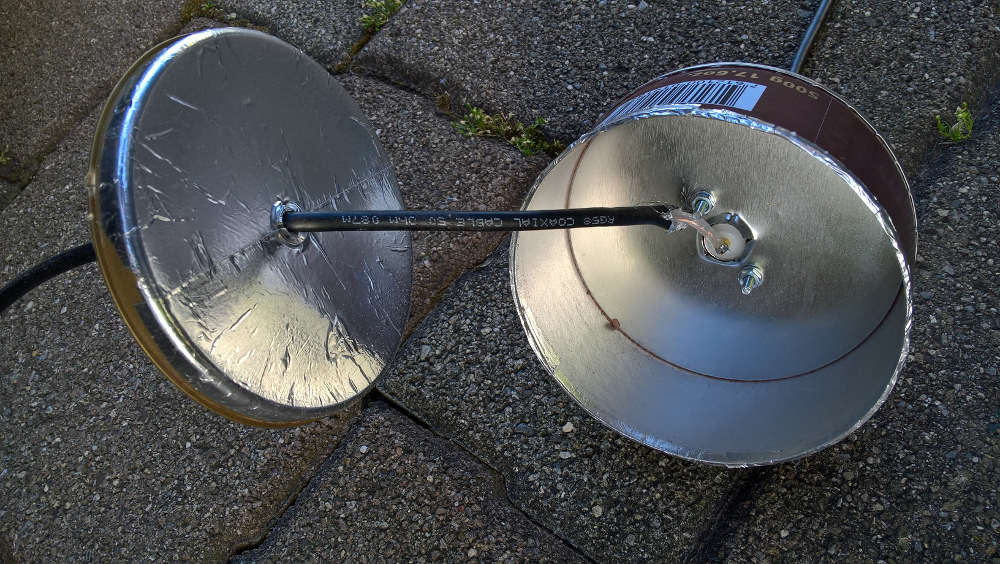
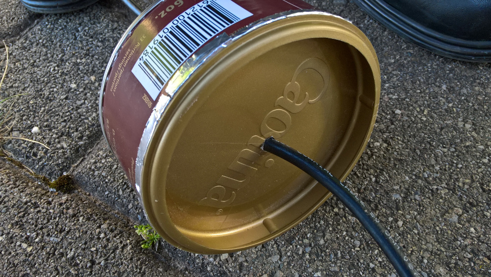
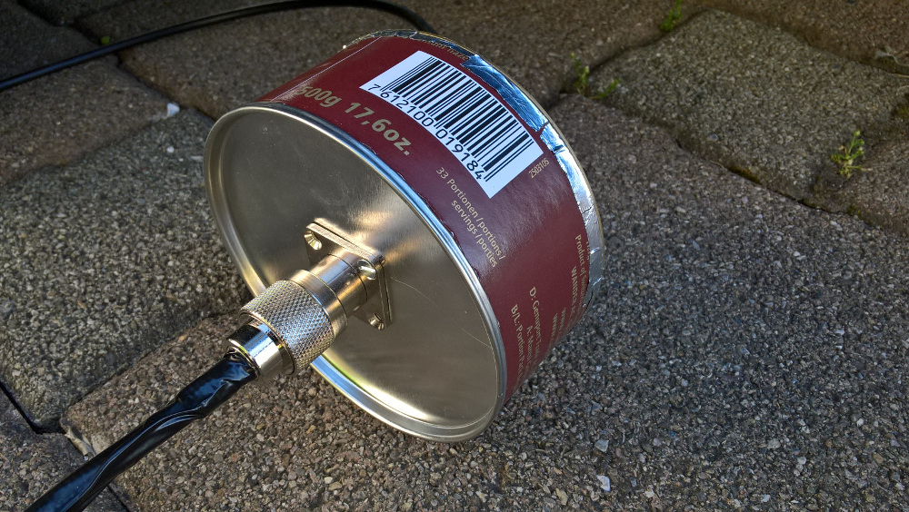
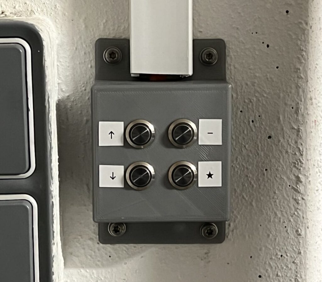
Zudem habe ich mir eine Handschaltbox an der Wand montiert, damit keine Fernbedienung zum Öffnen des Garagentors von innen benötigt wird.

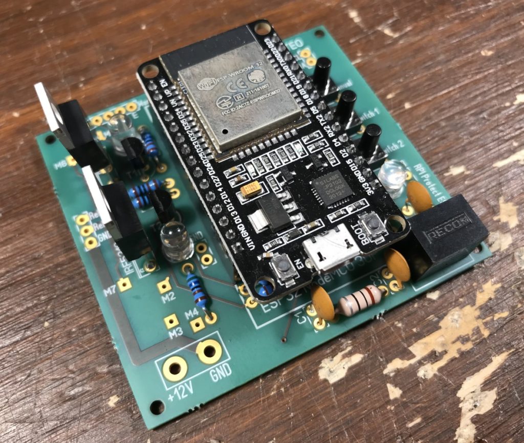
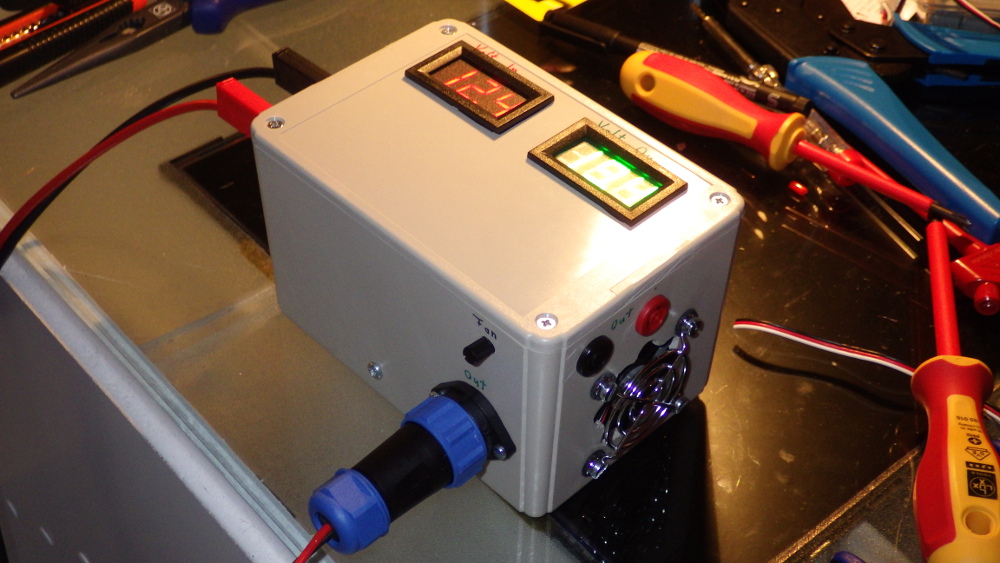
Elektronik
Die UAP 1 liefert 24V, diese speisen den ESP32 inklusive der Komponenten, die auf der Platine montiert sind. Die Transistoren werden vom ESP32 entsprechend geschalten.
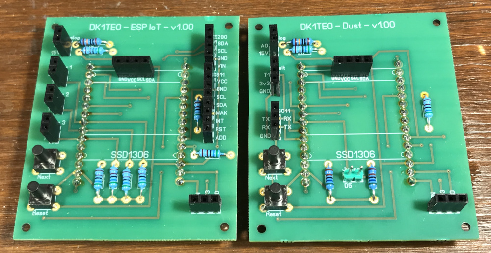
Hier die Platine dazu (Afillate): https://aisler.net/p/TITHFGRG
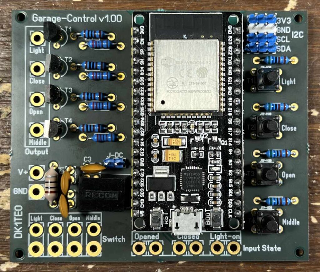
Links im Rahmen “Output” befinden sich die PINs, die beim Schalten des Garagentores durch den ESP32 entsprechend gegen Masse gezogen werden.
Die “Switch” Pins triggern das Schalten z.B. durch einen externen Schalter. Diese sind entsprechend entprellt durch das warten in der Software, sowie entsprechende Pull-Up Widerstände.
“Input State” sind die Anschlüsse für die Relais, mit denen das Garagentor den Status zurückmeldet.
Links oben befindet sich der I²C Anschluss, an diesen kann beispielsweise der BME280 Sensor angeschlossen werden.
Über V+ werden die Platine und der ESP32 bzw. zunächst der DC-Wandler mit Strom versorgt.
ACHTUNG! Wenn der Garagentorantrieb den Fehler zeigt, dass die Schlupftür im Garagentor noch geöffnet ist, muss man sicherstellen, dass alle Masseverbindungen der Eingänge an der UAP 1 entsprechend verbunden sind.
Bauteile
- C1, C2, C3 : 10nF
- L1 : 10 µH
- R1, R3, R5, R7 : 1kO
- R2, R4, R6, R8 : 2.2kO
- R9, R10, R11, R12, R13, R14, R15 : 5.6kO
- T1, T2, T3, T4 : BC547C
- DC-Wandler: RECOM R-78E50-05
- J-DC – Jumper; Ist dieser geschlossen, wird der ESP32 über den DC-Wandler versorgt, ist der Jumper nicht geschlossen, kann er beispielsweise zu Entwicklungszwecken über den PC versorgt werden.
Die Taster auf der rechten Seite der Platine sind optional.
Software
Der ESP32 besitzt eine JSON Schnittstelle mit dessen Hilfe er sich schalten lässt.
Um das Maß an Sicherheit zu erhöhen, wird OTP, also OneTimePassword, verwendet, ähnlich wie man es von der zwei Faktor Authentifizierung anderer Dienste kennt. Das soll verhindern, dass bei einem ungewollten Zugriff auf das Netzwerk, das Garagentor bedient werden kann.
Der ESP32 meldet aktiv den Status des Garagentors bei einer Änderung an den Home Assistant zurück. Ansonsten würde der Status erst dann aktualisiert werden, wenn Home Assistant die Daten via REST selbst abfragt. Dafür muss als Admin ein Dauer-Token erstellt werden und dieser der HTTP Anfrage im Header als “Bearer” beigefügt werden.
Über Disable Inputs lassen sich die Handschalter in der Garage deaktivieren.
Mit Disable Commands werden die Handschalter in der Garage und jegliche per JSON an das Gerät geschickte Commands deaktiviert.
Home Assistant
Das Garagentor habe ich in den Home Assistant integriert. Home Assistant unterstützt out-of-the-box die OTP Integration, auch für REST Kommandos.
Garagentor Steuerung-Schalter:
# Garagentor
switch:
  - platform: rest
    name: "ESP32 Garagentor - Open"
    resource: http://TorEspIp/jsondoaction
    method: post
    body_on: "{'doopen': '1', 'code': {{ states('sensor.garagentor_totp') }} }"
    body_off: "{'doopen': '0', 'code': {{ states('sensor.garagentor_totp') }} }"
    is_on_template: "{{ value_json.doopen }}"
    headers:
      Content-Type: application/json

  - platform: rest
    name: "ESP32 Garagentor - Close"
    resource: http://TorEspIp/jsondoaction
    method: post
    body_on: "{'doclose': '1', 'code': {{ states('sensor.garagentor_totp') }} }"
    body_off: "{'doclose': '0', 'code': {{ states('sensor.garagentor_totp') }} }"
    is_on_template: "{{ value_json.doclose }}"
    headers:
      Content-Type: application/json

  - platform: rest
    name: "ESP32 Garagentor - Middle"
    resource: http://TorEspIp/jsondoaction
    method: post
    body_on: "{'domiddle': '1', 'code': {{ states('sensor.garagentor_totp') }} }"
    body_off: "{'domiddle': '0', 'code': {{ states('sensor.garagentor_totp') }} }"
    is_on_template: "{{ value_json.domiddle }}"
    headers:
      Content-Type: application/json

  - platform: rest
    name: "ESP32 Garagentor - Light"
    resource: http://TorEspIp/jsondoaction
    method: post
    body_on: "{'dolight': '1', 'code': {{ states('sensor.garagentor_totp') }} }"
    body_off: "{'dolight': '0', 'code': {{ states('sensor.garagentor_totp') }} }"
    is_on_template: "{{ value_json.dolight }}"
    headers:
      Content-Type: application/json

  - platform: rest
    name: "ESP32 Garagentor - Disable Inputs"
    resource: http://TorEspIp/jsondoaction
    method: post
    body_on: "{'blockinputs': '1', 'code': {{ states('sensor.garagentor_totp') }} }"
    body_off: "{'blockinputs': '0', 'code': {{ states('sensor.garagentor_totp') }} }"
    is_on_template: "{{ value_json.blockinputs }}"
    headers:
      Content-Type: application/json

  - platform: rest
    name: "ESP32 Garagentor - Disable Commands"
    resource: http://TorEspIp/jsondoaction
    method: post
    body_on: "{'blockcommands': '1', 'code': {{ states('sensor.garagentor_totp') }} }"
    body_off: "{'blockcommands': '0', 'code': {{ states('sensor.garagentor_totp') }} }"
    is_on_template: "{{ value_json.blockcommands }}"
    headers:
      Content-Type: application/json
Garagentor Sensoren:
# Garagentor
rest:
  - scan_interval: 60
    resource: http://TorEspIp/jsondoaction
    sensor:
     - name: "ESP32 Garagentor - Request state"
       value_template: "{{ value_json.state }}"

     - name: "ESP32 Garagentor - Light state"
       value_template: "{{ value_json.light }}"

     - name: "ESP32 Garagentor - Close state"
       value_template: "{{ value_json.close }}"

     - name: "ESP32 Garagentor - Open state"
       value_template: "{{ value_json.open }}"

     - name: "ESP32 Garagentor - Doorstate"
       value_template: "{{ value_json.doorstate | int }}"

     - name: "ESP32 Garagentor - Doorstate text"
       value_template: "{{ value_json.doorstatetext }}"

     - name: "ESP32 Garagentor - Temperature"
       unit_of_measurement: "°C"
       value_template: "{{ value_json.bmeTemp | float }}"

     - name: "ESP32 Garagentor - Humidity"
       unit_of_measurement: "%"
       value_template: "{{ value_json.bmeHum | float }}"

     - name: "ESP32 Garagentor - Pressure"
       unit_of_measurement: "hPa"
       value_template: "{{ value_json.bmePress | float }}"

     - name: "ESP32 Garagentor - Free RAM"
       unit_of_measurement: "bytes"
       value_template: "{{ value_json.freeram | int }}"
OTP Generierung:
sensor:
  - platform: otp
    name: "Garagentor TOTP"
    token: YOURTOKENBASE32
Beim Token ist zu beachten, dass das “Secret” für das Hinterlegen im ESP32, sowie im Home Assistant BASE32 encodiert sein muss. Solche Konvertier gibt es unter anderem online. Wichtig ist, dass man von de Länge ein entsprechendes Secret wählt, dass am Ende keine Gleichzeiten im BASE32 stehen, da dies sonst zu Problemen führt.
Im ESP32 wird das BASE32 encodierte “Secret”, das für die OTP-Generierung benötigt wird als HEX hinterlegt.
Code
#include <ArduinoJson.h>
#include <HTTPClient.h>
#include <WebServer.h>
#include <WiFiClientSecure.h>
#include <TaskScheduler.h>
#include <Adafruit_Sensor.h>
#include <Adafruit_BME280.h>
#include <NTPClient.h>
#include <WiFiUdp.h>
#include <TOTP.h>
// --------- WIFI -----------
[...]
unsigned long previousMillis = 0;
unsigned long interval = 30000;
// --------- END WIFI -------
// --------- INITS -------
const char* ssid = STASSID;
const char* password = STAPSK;
const char* deviceName = DEVICENAME;
WiFiUDP ntpUDP;
NTPClient timeClient(ntpUDP, "de.pool.ntp.org", 0, 0);
WebServer server(80);
StaticJsonDocument<1024> jsonDocument;
char jsonBuffer[1024];
const String HomeAssistantBearerName = "Authorization";
const String HomeAssistantBearerContent = "Bearer XXXX";
const String SendApiIotUrl = "http://homeAssistantIp:8123/api/states/";
const String DoorStateIntName = "sensor.esp32_garagentor_doorstate";
const String DoorStateTextName = "sensor.esp32_garagentor_doorstate_text";
const String CloseStateBoolName = "sensor.esp32_garagentor_close_state";
const String OpenStateBoolName = "sensor.esp32_garagentor_open_state";
const String LighStateBoolName = "sensor.esp32_garagentor_light_state";
const String SwitchCloseStateName = "switch.esp32_garagentor_close";
const String SwitchMiddleStateName = "switch.esp32_garagentor_middle";
const String SwitchOpenStateName = "switch.esp32_garagentor_open";
const String SwitchLightStateName = "switch.esp32_garagentor_light";
Adafruit_BME280 bme; // I2C
// --------- END INITS -------
// --------- SCHEDULER BEGIN -------
void checkFreeRam();
Task scheduleCheckFreeRam(21*1000, TASK_FOREVER, &checkFreeRam);
void wifiReconnectCheck();
Task scheduleWifiReconnectCheck(8*60*1000, TASK_FOREVER, &wifiReconnectCheck);
void refreshTime();
Task scheduleRefreshTime(10*60*1000, TASK_FOREVER, &refreshTime);
void refreshTotp();
Task scheduleRefreshTotp(1*1000, TASK_FOREVER, &refreshTotp);
void refreshBmeVals();
Task scheduleRefreshBmeVals(20*1000, TASK_FOREVER, &refreshBmeVals);
Scheduler runner;
// --------- SCHEDULER END ---------
// ------- DEFINITIONS ----------
static int selfCheckPinDuration = 500;
static String linkColorNormal = "#2321B0";
static String linkColorVisited = "#2321B0";
static String activeMarkerBegin = "<b>»";
static String activeMarkerEnd = "«</b>";
static String textState[] = {"unknown", "closed", "moving / half-open", "open"};
// ------- END DEFINITIONS ----------
// ------- PINS ----------
static int morsePin = 2;
static int i2cSdaPin = 21;
static int i2cSclPin = 22;
static int pinOutLight = 32;
static int pinOutClose = 25;
static int pinOutOpen = 26;
static int pinOutMiddle = 27;
static int pinInStateOpened = 23;
static int pinInStateClosed = 33;
static int pinInStateLight = 16;
static int pinInSwitchLight = 19;
static int pinInSwitchClose = 18;
static int pinInSwitchOpen = 17;
static int pinInSwitchMiddle = 15;
// ------- END PINS ----------
// --------- Variables ---------
int freeHeap = 0;
bool blockInputs = false;
bool blockCommands = false;
String bmeTemp = String("");
String bmeHum = String("");
String bmePress = String("");
// 0 unknown
// 1 closed
// 2 moving / in between
// 3 open
int doorState = 0;
bool openState = false;
bool closeState = false;
bool lightState = false;
bool lightButton = false;
bool closeButton = false;
bool openButton = false;
bool middleButton = false;
// otp
String totpOldCode = String("");
String totpActualCode = String("");
uint8_t hmacKey[] = { 0x00, [...]};
TOTP totp = TOTP(hmacKey, 20);
// --------- END Variables ---------
void setup()
{
// put your setup code here, to run once:
initSerial();
initWifi();
initSchedules();
initPinModes();
initBme();
initTimeClient();
initServer();
refreshTotp();
checkFreeRam();
}
void loop()
{
handleInputs();
server.handleClient();
resetPendingCommands();
handleActions();
runner.execute();
}
void initSerial()
{
Serial.begin(115200);
while(!Serial){} // Waiting for serial connection
Serial.println();
}
void initWifi()
{
[...]
Serial.println(WiFi.localIP());
}
void initPinModes()
{
Serial.println("PIN MODES init");
pinMode(morsePin, OUTPUT);
digitalWrite(morsePin, LOW);
pinMode(pinOutLight, OUTPUT);
digitalWrite(pinOutLight, LOW);
pinMode(pinOutClose, OUTPUT);
digitalWrite(pinOutClose, LOW);
pinMode(pinOutOpen, OUTPUT);
digitalWrite(pinOutOpen, LOW);
pinMode(pinOutMiddle, OUTPUT);
digitalWrite(pinOutMiddle, LOW);
pinMode(pinInStateOpened, INPUT);
pinMode(pinInStateClosed, INPUT);
pinMode(pinInStateLight, INPUT);
pinMode(pinInSwitchLight, INPUT);
pinMode(pinInSwitchClose, INPUT);
pinMode(pinInSwitchOpen, INPUT);
pinMode(pinInSwitchMiddle, INPUT);
}
void initBme()
{
// BME 280
for(int i = 0; i < 10; i++)
{
Serial.println("detecting BME280...");
delay(500);
if (bme.begin(0x76))
{
i = 10;
}
}
}
void initSchedules()
{
Serial.println("SCHEDULES init");
runner.init();
runner.addTask(scheduleCheckFreeRam);
scheduleCheckFreeRam.enable();
runner.addTask(scheduleWifiReconnectCheck);
scheduleWifiReconnectCheck.enable();
runner.addTask(scheduleRefreshTime);
scheduleRefreshTime.enable();
runner.addTask(scheduleRefreshTotp);
scheduleRefreshTotp.enable();
runner.addTask(scheduleRefreshBmeVals);
scheduleRefreshBmeVals.enable();
}
void initTimeClient()
{
timeClient.begin();
delay(1000);
timeClient.update();
}
void initServer()
{
server.on("/", handleConnect);
server.on("/jsondoaction", jsonDoAct);
server.on("/jsondoaction", HTTP_POST, jsonDoAct);
server.onNotFound(handleConnect);
server.begin();
Serial.println("HTTP server started");
}
void refreshTotp()
{
String newCode = String(totp.getCode(timeClient.getEpochTime()));
if(totpActualCode != newCode)
{
totpOldCode = totpActualCode;
totpActualCode = String(newCode);
Serial.print("TOTP code: ");
Serial.println(newCode);
Serial.println(timeClient.getEpochTime());
}
}
void refreshBmeVals()
{
Serial.println("Refresh BME Vals");
String zBmeTemp = String(bme.readTemperature());
String zBmeHum = String(bme.readHumidity());
String zBmePress = String(bme.readPressure() / 100.0F);
bmeTemp = zBmeTemp;
bmeHum = zBmeHum;
bmePress = zBmePress;
Serial.println("END - Refresh BME Vals");
}
void wifiReconnectCheck()
{
unsigned long currentMillis = millis();
// if WiFi is down, try reconnecting every CHECK_WIFI_TIME seconds
if ((WiFi.status() != WL_CONNECTED) && (currentMillis - previousMillis >=interval))
{
Serial.print(millis());
Serial.println("Reconnecting to WiFi...");
WiFi.disconnect();
WiFi.reconnect();
previousMillis = currentMillis;
}
}
void refreshTime()
{
timeClient.update();
}
void checkFreeRam()
{
freeHeap = ESP.getFreeHeap();
if (ESP.getFreeHeap() < 60000)
{
ESP.restart();
}
}
bool totpValid(String codeToCheck)
{
if (codeToCheck == totpOldCode ||
codeToCheck == totpActualCode)
{
return true;
}
return false;
}
void handleInputs()
{
int tmpState = 0;
bool changedStateRelais = false;
// open state
tmpState = digitalRead(pinInStateOpened);
if (tmpState == 1)
{
if (changedBool(openState, true))
{
sendStatusChangeBool(OpenStateBoolName, true);
changedStateRelais = true;
}
openState = true;
}
else
{
if (changedBool(openState, false))
{
sendStatusChangeBool(OpenStateBoolName, false);
changedStateRelais = true;
}
openState = false;
}
// close state
tmpState = digitalRead(pinInStateClosed);
if (tmpState == 1)
{
if (changedBool(closeState, true))
{
sendStatusChangeBool(CloseStateBoolName, true);
changedStateRelais = true;
}
closeState = true;
}
else
{
if (changedBool(closeState, false))
{
sendStatusChangeBool(CloseStateBoolName, false);
changedStateRelais = true;
}
closeState = false;
}
// handle door status
if (changedStateRelais == true)
{
if (openState == false &&
closeState == false)
{
doorState = 2;
}
else if (openState == true &&
closeState == true)
{
doorState = 0;
}
else if (openState == true)
{
doorState = 3;
}
else if (closeState == true)
{
doorState = 1;
}
sendStatusChangeInt(DoorStateIntName, doorState);
sendInputStatusHttp(DoorStateTextName, getStatusText(), true);
}
// light state
tmpState = digitalRead(pinInStateLight);
if (tmpState == 1)
{
if (changedBool(lightState, true))
{
sendStatusChangeBool(LighStateBoolName, true);
}
lightState = true;
}
else
{
if (changedBool(lightState, false))
{
sendStatusChangeBool(LighStateBoolName, false);
}
lightState = false;
}
if (blockInputs == false)
{
// BUTTONS / SWITCHES
if (blockInputs == false)
{
tmpState = buttonPressed(pinInSwitchLight);
if (tmpState == 1)
{
if (changedBool(lightButton, true))
{
sendStatusChangeSwitch(SwitchLightStateName, true);
}
lightButton = true;
}
else
{
if (changedBool(lightButton, false))
{
sendStatusChangeSwitch(SwitchLightStateName, false);
}
lightButton = false;
}
tmpState = buttonPressed(pinInSwitchClose);
if (tmpState == 1)
{
if (changedBool(closeButton, true))
{
sendStatusChangeSwitch(SwitchCloseStateName, true);
}
closeButton = true;
}
else
{
if (changedBool(closeButton, false))
{
sendStatusChangeSwitch(SwitchCloseStateName, false);
}
closeButton = false;
}
tmpState = buttonPressed(pinInSwitchOpen);
if (tmpState == 1)
{
if (changedBool(openButton, true))
{
sendStatusChangeSwitch(SwitchOpenStateName, true);
}
openButton = true;
}
else
{
if (changedBool(openButton, false))
{
sendStatusChangeSwitch(SwitchOpenStateName, false);
}
openButton = false;
}
tmpState = buttonPressed(pinInSwitchMiddle);
if (tmpState == 1)
{
if (changedBool(middleButton, true))
{
sendStatusChangeSwitch(SwitchMiddleStateName, true);
}
middleButton = true;
}
else
{
if (changedBool(middleButton, false))
{
sendStatusChangeSwitch(SwitchMiddleStateName, false);
}
middleButton = false;
}
}
}
}
int buttonPressed(int buttonNumber)
{
int tmpState = 0;
tmpState = digitalRead(buttonNumber);
if (tmpState == 0)
{
digitalWrite(morsePin, HIGH);
delay(20);
tmpState = digitalRead(buttonNumber);
delay(100);
digitalWrite(morsePin, LOW);
if (tmpState == 0)
{
Serial.println("Button Pressed: " + String(buttonNumber));
return 1;
}
}
return 0;
}
bool changedBool(bool before, bool after)
{
if(before != after)
{
return true;
}
return false;
}
bool changedInt(int before, int after)
{
if (before != after)
{
return true;
}
return false;
}
void sendStatusChangeBool(String attributeStringIn, bool valueIn)
{
if (valueIn == true)
{
Serial.println(sendInputStatusHttp(attributeStringIn, "true", false));
}
else
{
Serial.println(sendInputStatusHttp(attributeStringIn, "false", false));
}
}
void sendStatusChangeInt(String attributeStringIn, int valueIn)
{
Serial.println(sendInputStatusHttp(attributeStringIn, String(valueIn), false));
}
void sendStatusChangeSwitch(String attributeStringIn, bool valueIn)
{
Serial.println(sendInputStatusHttp(attributeStringIn, boolToSwitch(valueIn), true));
}
void resetPendingCommands()
{
if (blockInputs == true &&
blockCommands == true)
{
lightButton = false;
closeButton = false;
openButton = false;
middleButton = false;
}
}
void handleActions()
{
int hiTimer = 800; // ms
if (lightButton == true)
{
digitalWrite(morsePin, HIGH);
digitalWrite(pinOutLight, HIGH);
delay(hiTimer);
digitalWrite(pinOutLight, LOW);
digitalWrite(morsePin, LOW);
if (changedBool(lightButton, false))
{
sendStatusChangeSwitch(SwitchLightStateName, false);
}
lightButton = false;
}
else if (closeButton == true)
{
digitalWrite(morsePin, HIGH);
digitalWrite(pinOutClose, HIGH);
delay(hiTimer);
digitalWrite(pinOutClose, LOW);
digitalWrite(morsePin, LOW);
if (changedBool(closeButton, false))
{
sendStatusChangeSwitch(SwitchCloseStateName, false);
}
closeButton = false;
}
else if (openButton == true)
{
digitalWrite(morsePin, HIGH);
digitalWrite(pinOutOpen, HIGH);
delay(hiTimer);
digitalWrite(pinOutOpen, LOW);
digitalWrite(morsePin, LOW);
if (changedBool(openButton, false))
{
sendStatusChangeSwitch(SwitchOpenStateName, false);
}
openButton = false;
}
else if (middleButton == true)
{
digitalWrite(morsePin, HIGH);
digitalWrite(pinOutMiddle, HIGH);
delay(hiTimer);
digitalWrite(pinOutMiddle, LOW);
digitalWrite(morsePin, LOW);
if (changedBool(middleButton, false))
{
sendStatusChangeSwitch(SwitchMiddleStateName, false);
}
middleButton = false;
}
}
String getStatusText()
{
return textState[doorState];
}
// HTTP Server
void handleConnect()
{
Serial.println("Connect");
server.send(200, "text/html", SendHTML(""));
}
String SendHTML(String context)
{
String ptr = "<!DOCTYPE html> <html>\n";
ptr +="<head><meta name=\"viewport\" content=\"width=device-width, initial-scale=1.0, user-scalable=no\">\n";
ptr +="<title>ESP32 Garagentor</title>\n";
ptr +="<style>html { font-family: Arial; display: inline-block; margin: 0px auto; text-align: center;}\n";
ptr +="body{margin-top: 50px;} h1 {color: #444444;margin: 50px auto 30px;} h3 {color: #444444;margin-bottom: 50px;}\n";
ptr +=".button {display: block;width: 80px;background-color: #3498db;border: none;color: white;padding: 13px 30px;text-decoration: none;font-size: 25px;margin: 0px auto 35px;cursor: pointer;border-radius: 4px;}\n";
ptr +="a, a:active, { color: " + linkColorNormal + "; text-decoration: underline; }\n";
ptr +="a:visited { color: " + linkColorVisited + "; text-decoration: underline; }\n";
ptr +="p {font-size: 14px;color: #888;margin-bottom: 10px;}\n";
ptr +="</style>\n";
ptr +="</head>\n";
ptr +="<body>\n";
ptr +="<h1>ESP32 Garagentor</h1>\n";
String lineBreak = "<br><br>";
ptr += ""; // TODO
ptr +="</body>\n";
ptr +="</html>\n";
return ptr;
}
void jsonDoAct()
{
Serial.println("JSON Act");
String status = "IDLE";
int tmpInput = 0;
bool waitAfterResponse = false;
if (server.hasArg("plain") == false)
{
//handle error here
}
String body = server.arg("plain");
Serial.println(body);
deserializeJson(jsonDocument, body);
if (jsonDocument.containsKey("code") == true)
{
String code = jsonDocument["code"];
if (totpValid(code) == true)
{
// continue
status = "OK";
if (jsonDocument.containsKey("blockinputs") == true)
{
tmpInput = jsonDocument["blockinputs"];
if (tmpInput == 1)
{
blockInputs = true;
}
else
{
blockInputs = false;
}
}
else if (jsonDocument.containsKey("blockcommands") == true)
{
tmpInput = jsonDocument["blockcommands"];
if (tmpInput == 1)
{
blockCommands = true;
}
else
{
blockCommands = false;
}
}
else if (jsonDocument.containsKey("dolight") == true &&
blockCommands == false)
{
tmpInput = jsonDocument["dolight"];
if (tmpInput == 1)
{
lightButton = true;
waitAfterResponse = true;
}
else
{
lightButton = false;
}
}
else if (jsonDocument.containsKey("doclose") == true &&
blockCommands == false)
{
tmpInput = jsonDocument["doclose"];
if (tmpInput == 1)
{
closeButton = true;
waitAfterResponse = true;
}
else
{
closeButton = false;
}
}
else if (jsonDocument.containsKey("doopen") == true &&
blockCommands == false)
{
tmpInput = jsonDocument["doopen"];
if (tmpInput == 1)
{
openButton = true;
waitAfterResponse = true;
}
else
{
openButton = false;
}
}
else if (jsonDocument.containsKey("domiddle") == true &&
blockCommands == false)
{
tmpInput = jsonDocument["domiddle"];
if (tmpInput == 1)
{
middleButton = true;
waitAfterResponse = true;
}
else
{
middleButton = false;
}
}
}
else
{
status = "ERROR: WRONG CODE";
}
Serial.println(status);
}
resetPendingCommands();
createStatusJson(status);
server.send(200, "application/json", jsonBuffer);
if (waitAfterResponse == true)
{
//delay(500);
}
}
// -------------------- JSON HELPER --------------------------
void createStatusJson(String statusIn)
{
if (statusIn == "")
{
statusIn = "OK";
}
jsonDocument.clear();
jsonDocument["state"] = statusIn;
jsonDocument["dolight"] = lightButton;
jsonDocument["doclose"] = closeButton;
jsonDocument["doopen"] = openButton;
jsonDocument["domiddle"] = middleButton;
jsonDocument["blockinputs"] = blockInputs;
jsonDocument["blockcommands"] = blockCommands;
jsonDocument["light"] = lightState;
jsonDocument["close"] = closeState;
jsonDocument["open"] = openState;
jsonDocument["doorstate"] = doorState;
jsonDocument["doorstatetext"] = getStatusText();
if (bmePress != String("") &&
bmePress.toFloat() > 0)
{
jsonDocument["bmeTemp"] = bmeTemp;
jsonDocument["bmeHum"] = bmeHum;
jsonDocument["bmePress"] = bmePress;
}
jsonDocument["freeram"] = freeHeap;
serializeJson(jsonDocument, jsonBuffer);
}
String boolToSwitch(bool inVal)
{
if (inVal == true)
{
return "on";
}
return "off";
}
// -------------------- HTTP HELPER --------------------------
String sendInputStatusHttp(String attributeStringIn, String valueIn, bool isString)
{
String retStr;
HTTPClient *http = new HTTPClient();
http->setReuse(false);
Serial.print("[HTTP] begin...\n");
Serial.println("[HTTP] URL: " + SendApiIotUrl + attributeStringIn);
if (http->begin(SendApiIotUrl + attributeStringIn))
{
Serial.print("[HTTP] POST...\n");
http->setTimeout(5000);
// start connection and send HTTP header
http->addHeader("Content-Type", "application/json; charset=UTF-8");
http->addHeader(HomeAssistantBearerName, HomeAssistantBearerContent); // auth
// status Json
String sendContent = "";
if (isString == true)
{
sendContent = "{\"state\": \""+valueIn+"\" }";
}
else
{
sendContent = "{\"state\": "+valueIn+" }";
}
Serial.println("Content: " + sendContent);
int httpCode = http->POST(sendContent);
// httpCode will be negative on error
if (httpCode > 0)
{
// HTTP header has been send and Server response header has been handled
Serial.printf("[HTTP] POST... code: %d\n", httpCode);
// file found at server
if (httpCode == HTTP_CODE_OK || httpCode == HTTP_CODE_MOVED_PERMANENTLY)
{
//String payload = http->getString();
//Serial.println(payload);
retStr = http->getString();
}
//String payload = http->getString();
//Serial.println(payload);
}
else
{
Serial.printf("[HTTP] GET... failed, error: %s\n", http->errorToString(httpCode).c_str());
retStr = "error: ";
retStr += http->errorToString(httpCode).c_str();
}
http->end();
}
else
{
Serial.printf("[HTTP] Unable to connect\n");
retStr = "ConErr";
}
delete http;
http = NULL;
return retStr;
}Hinweis
Dieser Artikel dokumentiert lediglich meinen Aufbau. Für den Nachbau, die Nutzung einzelner Komponenten, die Platinen und den gesamten Inhalt wird die Haftung in jeglicher Form ausgeschlossen.